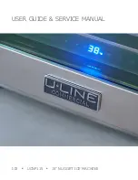
background image

USER GUIDE & SERVICE MANUAL

ICE   

   UCNP115   

   15” NUGGET ICE MACHINE

Summary of Contents for UCNP115

Page 1: ...USER GUIDE SERVICE MANUAL ICE UCNP115 15 NUGGET ICE MACHINE...

Page 2: ...cket General Installation Grille Installation Door Swing Door Adjust Maintenance Cleaning Cleaning Condenser Extended Non Use Operating Instructions Control Operation Ice Airflow and Product Loading S...

Page 3: ...lect products are available worldwide PRODUCT INFORMATION Looking for additional information on your product User Guides Spec Sheets CAD Drawings Compliance Documentation and Product Warranty informat...

Page 4: ...gular use Do not use sharp objects to expedite defrosting Do not service without consulting the R600a specifications section included in the User Guide Do not damage the refrigerant circuit Service mu...

Page 5: ...n place so children may not easily climb inside If the unit is being removed from service for disposal check and obey all federal state and local regulations regarding the disposal and recycling of re...

Page 6: ...or reduce ice production on applicable models For best performance keep the unit out of direct sunlight and away from heat generating equipment In climates where high humidity and dew points are prese...

Page 7: ...he unit Always keep your working area dry NOTICE Electrical installation must observe all state and local codes This unit requires connection to a grounded three prong polarized receptacle that has be...

Page 8: ...n the face of the unit with other adjacent cabinet doors you may need to alter the wall just behind the drain connection on the unit to accommodate the drain CUTOUT DIMENSIONS 15 Cutout width sufficie...

Page 9: ...ed according to each unit s electrical specifications requirements Side by Side Installation with Bracket 1 Slide both units out so screws on top of units are easily accessible 2 Remove screws as show...

Page 10: ...ge 1x per year Optional Large Filter Change 1x per year 401 600 TDS and or 13 20 gpg hardness Required Large Filter Change 1x per year Required Large Filter Change 2x per year 601 TDS and or 21 gpg ha...

Page 11: ...UIDE u line com Water Hookup 3 Thread water line through back panel hole with bushing 4 Locate water valve inlet and connect to valve 5 Turn on water supply and check for leaks 6 Reinstall back panel...

Page 12: ...low the unit Unit has a solid base that will not allow the unit to drain below itself There is a possibility that hose connections may have loosened during shipment Verify all connections and fittings...

Page 13: ...e installed U Line P60 drain pump If you need to install a P60 drain pump into your unit see DRAIN PUMP section in the User Manual See below for typical installations requiring a drain pump FACTORY IN...

Page 14: ...ver holes and attach to unit with two screws removed in step 2 using a T 25 Torx driver Tighten screws fully 4 Gently push unit into position Be careful not to entangle the electrical cord or water li...

Page 15: ...eve a total unit rear height of 1 8 3 mm less than opening s rear height Shorten the unit height in the front by adjusting the front legs This allows the unit to be gently tipped into the opening Read...

Page 16: ...e unit the grille must be installed WARNING DO NOT touch the condenser fins The condenser fins are SHARP and can be easily damaged Removing the grille 1 Disconnect power to the unit 2 Loosen the two s...

Page 17: ...ng Units have a zero clearance for the door to open 90 when installed adjacent to cabinets Stainless Steel models require 2 1 8 54 mm door clearance to accommodate the handle if installed next to a wa...

Page 18: ...en do not remove top and bottom hinge screws using a Torx T 25 screwdriver 3 Align door squarely with cabinet 4 Make sure gasket is firmly in contact with cabinet all the way around the door no gaps 5...

Page 19: ...om hinge 1 Remove bottom hinge from cabinet using a 1 4 socket 2 Remove corresponding screws on opposite side of cabinet On some models there may be a nut behind one or both screws on either side Inst...

Page 20: ...h Mode Press and release Display and interior light return to normal operation Clean Mode See Cleaning section Showroom Mode Hold and for 5 seconds The F C symbol will flash Display will be lit and in...

Page 21: ...production resumes This ensures a constant supply of fresh ice is always available The factory default ice setting is 0 which produces a firm and compact ice nugget U Line s exclusive U Choose ice ad...

Page 22: ...u line com Airflow and Product Loading NOTICE The unit requires proper airflow to perform at its highest efficiency Do not block the front grille at any time or the unit will not perform as expected D...

Page 23: ...of the rust may not be possible CLEAN INTERIOR COMPONENTS Use warm or hot water with dish soap to clean all removed components and interior surfaces You may use a vinegar and water solution in place o...

Page 24: ...t ice inside the dispenser tube It is normal for some water to flow Cl NUGGET ICE MACHINE CLEANING CYCLE This ice machine has an automatic clean alert function The control will indicate CL in the disp...

Page 25: ...and a sponge to wipe down the inside of the ice bin and scoop Rinse with clean potable water 6 When 05 appears in the display 3 soft tones will sound indicating the cleaning phase is complete a Remov...

Page 26: ...nvironmental conditions more or less frequent cleaning may be necessary WARNING Disconnect electric power to the unit before cleaning the condenser NOTICE DO NOT use any type of cleaner on the condens...

Page 27: ...r must remain open to prevent formation of mold and mildew Open door a minimum of 2 50 mm to provide the necessary ventilation WINTERIZATION If the unit will be exposed to temperatures of 40 F 5 C or...

Page 28: ...ompressor makes a hum or pulsing sound that may be heard when it operates BEFORE CALLING FOR SERVICE TROUBLESHOOTING GUIDE ELECTROCUTION HAZARD Never attempt to repair or perform maintenance on the un...

Page 29: ...ng the testing period 6 After 24 hours check the temperature of the water If required adjust the temperature control in a small increment see CONTROL OPERATION Causes which affect the internal tempera...

Page 30: ...Purple Black Yellow Open Black White FUSE N C 11 22 1 10 1 1 5 1 6 1 4 12 Pump White light Bin temp Door switch Pump Low water sensor Water shutoff Dump Valve Resevoir Valve Auger Condenser Fan Open...

Page 31: ...zed to replace the part in question The part that caused the damage must be returned to U Line in its entirety The part must be clearly labeled with the serial number of the unit it was removed from t...

Page 32: ...ing for warranty labor Units must be registered prior to warranty submittal Customers may register at www U Line com A proof of purchase is required We also accept the following information to update...

Page 33: ...80 55538 00 15 GASKET NUG ADA 80 55396 00 16 GRILLE ASSY NUG OUTDR 80 55389 00 17 HEAT EXCHANGER NUGGET 80 55434 00 18 HINGE ASSY 15 PIVOT 80 55219 00 19 HINGE COVER OUTDOOR 80 55499 00 20 ICE MACHIN...

Page 34: ...80 55371 06 7 EVAPORATOR ASSY W INSULATION 80 55371 07 8 HOUSING BUSHING W INSULATION 80 55371 08 9 HARDWARE KIT GEAR MOTOR 80 55371 09 10 RESERVOIR FLOAT COMPLETE ASSY 80 55371 10 11 LID RESERVOIR O...

Page 35: ...rovide the model serial number part number and part description Some parts will require color or voltage information If U Line requires the return of original parts we will inform you when the parts o...

Page 36: ...cian must observe all federal state and local laws regarding refrigerants Gloves and Eye Protection must be used R 600a is considered non toxic but is flammable when mixed with air Keep a dry powder t...

Page 37: ...cuum pump and recovery equipment should be at least 10 feet from the work area It is recommended that a simple LPG gas detector is on site during service Ensure that all R 600a is removed from the sys...

Page 38: ...erant is left within the system prior to repair simple venting is not sufficient Evacuate and charge with dry nitrogen for leak checks Repair leaks or replace system parts as required When re brazing...

Page 39: ...Install a Schrader Type access port on the compressor process stub Evacuate the system to 100 microns prior to charging Weigh in the R 600a charge using a refrigerant scale run compressor an extra two...

Page 40: ...erature Hot Warm Warm Extremely cold near inlet Outlet below room temperature Lower than normal Partial Restriction Somewhat lower than normal vacuum Warm near room temperature Very hot Top passes war...

Page 41: ...h are not hot or frozen Do not touch a bare circuit board unless you are wearing an anti static wrist strap that is grounded to an electrical ground or grounded water pipe Handle circuit boards carefu...

Page 42: ...2547 for assistance NORMAL OPERATING SOUNDS All models incorporate rigid foam insulated cabinets to provide high thermal efficiency and maximum sound reduction for its internal working components Des...

Page 43: ...Mode OHM thermistor Frost Buildup Inside Unit Door Ajar or Restricted from Closing Check door clearance to adjoining cabinetry Check distribution of product in unit Thermistor failure OHM thermistor...

Page 44: ...e Plunger Switch Replace Main Board Replace Fuse Replace Power Cord Alert Customer Of Power Failure Is the Plunger Switch Operating Properly Inspect Customer UI and Data Cable Connect Test Display Cyc...

Page 45: ...the display This mode can be canceled by pressing and releasing The mode will automatically be changed back to ON after three hours SHOWROOM MODE This mode is designed to show units in a display envir...

Page 46: ...g Period frequency that data is output to diagnostics port 27 Factory test mode 0 Off 1 On 28 Compressor RPM 29 Freeze time adjust Model 54 only 30 Harvest time adjust Model 54 only 31 Low temp alarm...

Page 47: ...operly 23 ACTIVATE DEFROST HARVEST Press and hold for 3 seconds to activate 24 FACTORY DEFAULTS Press and hold for 3 seconds to restore all values to factory defaults 25 MAIN SOFTWARE 26 Does not appl...

Page 48: ...A 38 HWC524 1A 39 HWC524 2A 40 HWC336 1A 41 HBD324 1A 42 HBD324 2A 43 HBD524 1A 44 HBD524 2A 45 HWD324 2A 46 HWD324 1A 47 HWD524 2A 48 HWD524 1A 49 HRF124 2A 50 HRF124 1A 51 HRI124 2A 52 HRI124 1A 53...

Page 49: ...Light 2 Evap Fan Cond Fan 22 RE336 1A Compressor Top Left Valve Bot Right Valve Light 1 Light 2 Evap Fan Evap Fan 2 Cond Fan 23 RE515 1A Compressor Light 1 Light 2 Evap Fan Cond Fan 25 RE524 1A Compre...

Page 50: ...ns Dielectric grease will help to keep thermistor connections clean and dry If you change a thermistor in the unit please re apply dielectric grease to the connection If you encounter a dirty thermist...

Page 51: ...d or other natural disasters The product must be installed operated and maintained in accordance with your product s User Guide The remedies described above for each warranty are the only ones that U...

Reviews: