background image

USER GUIDE

u-line.com

Anti-Tip Bracket

Anti-Tip Bracket

Use one of the methods below to secure the unit

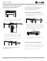
CABINET/COUNTER ANTI-TIP INSTALLATION

     (For built-in applications)

1.  Slide unit out so screws on front of unit are easily         

accessible.

2.  Remove the two screws from the front of the unit.


3.  Bend bracket along one of the perforations to allow 

attachment to the desired adjoining surface.

4.  Gently push unit into position. Be careful not to 

entangle the electrical cord or water line, if applicable.

5.  Check to be sure the unit is level from front to back 

and side to side. Make any necessary adjustments. 
The unit’s top surface should be approximately 

1⁄8

”     

(3 mm) below the countertop.

6.  Secure bracket to adjoining surface.

FLOOR MOUNTED ANTI-TIP INSTALLATION

     (For free-standing applications)

1.  Locate two anti-tip brackets included with the kit.

2.  Place the unit into the area where it will be installed. 

Check the door, sides, and top for a proper fit. Also 

test to make sure the door opens and closes freely.

3. 

Remove grille and place a mark on the floor at the 
front of the unit. Also place a mark on the floor in the 

center of the unit.

4.  Remove the unit. Using a square, extend center line 

“B” (see chart below). This line serves as the back 
edge for the anti-tip brackets. From the center line, 

measure “A” to the left and right. This line is the outer 

edge of each bracket.

CL

Back wall

Back of unit

Front of unit

Surrounding

area (Top view)

A

A

B

515

518

524

A

5⁄8”

9”

11 

15⁄16

B

22”

22”

22”

5. 

Place the anti-tip brackets on the floor against the line 

drawn for the outer edge. Mark spots for the screw 
holes.

C

L

Surrounding

area (Top view)

Drill holes and

mount anti-tip

brackets to floor

Back wall

Front

of 

unit

Back

of 

unit

A

A

B

6.  Use a 1/8” drill to make two starter holes and fasten 

the anti-tip brackets to the floor using the screws 

provided.

7.  Place the unit back into position, making sure the 

feet engage the anti-tip brackets properly. Check 

the alignment of the lines made on the floor in step 

3 with the position of the front feet to ensure proper 
positioning.

10

Summary of Contents for UHBV524

Page 1: ...USER GUIDE SERVICE MANUAL 5 Class UHBV524 24 Beverage Center...

Page 2: ...ironmental Requirements Electrical Cutout Product Dimensions Side by Side Installation Anti Tip Bracket General Installation Grille Installation Door Swing Door Adjust Operating Instructions First Use...

Page 3: ...over two decades and is proud to have the opportunity to ship to you PRODUCT INFORMATION Looking for additional information on your product User Guides Spec Sheets CAD Drawings Compliance Documentatio...

Page 4: ...th CAUTION Caution means that failure to follow this safety statement may result in minor or moderate personal injury property or equipment damage DANGER This unit contains R600a Isobutane which is a...

Page 5: ...n place so children may not easily climb inside If the unit is being removed from service for disposal check and obey all federal state and local regulations regarding the disposal and recycling of re...

Page 6: ...mperatures may reduce the unit s ability to reach low temperatures and or reduce ice production on applicable models For best performance keep the unit out of direct sunlight and away from heat genera...

Page 7: ...he unit Always keep your working area dry NOTICE Electrical installation must observe all state and local codes This unit requires connection to a grounded three prong polarized receptacle that has be...

Page 8: ...ectrical connection in the rear CAUTION Unit can NOT be installed behind a closed cabinet door CUTOUT DIMENSIONS PRODUCT DIMENSIONS REAR FRONT TOP SIDE 4 102 mm 7 178 mm 33 7 8 860 mm to 34 7 8 886 mm...

Page 9: ...on Guide Each door can be opened individually one at a time without interference However to ensure unobstructed door swing opening both doors at the same time 1 4 6 4 mm of space needs to be maintaine...

Page 10: ...r a proper fit Also test to make sure the door opens and closes freely 3 Remove grille and place a mark on the floor at the front of the unit Also place a mark on the floor in the center of the unit 4...

Page 11: ...s than the opening s rear height Shorten the unit height in the front by adjusting the front legs This allows the unit to be gently tipped into the opening Readjust the front legs to level the unit af...

Page 12: ...e unit the grille must be installed WARNING DO NOT touch the condenser fins The condenser fins are SHARP and can be easily damaged Removing the grille 1 Disconnect power to the unit 2 Loosen the two s...

Page 13: ...itional space for any knobs or pulls installed on the integrated panel frame Stainless Steel models that are installed adjacent to a wall require 2 1 4 57 mm door clearance on hinge side to allow for...

Page 14: ...en each pair of Torx head screws both the upper and lower hinge plates 3 Square and align door as necessary 4 Tighten Torx head screws on hinge 5 Reinstall gasket into the channel starting at the corn...

Page 15: ...as turned off during installation simply press and the unit will immediately switch on To turn the unit off press If the temperature displayed is different than selected the unit is progressing toward...

Page 16: ...ust light color While holding press and release to scroll through lighting options Option Open Door Closed Door 00 White White 01 Blue Blue 02 White Blue Light will be set at full intensity when door...

Page 17: ...ies U Line uses the following sizes Combinations of red and white bottles are used in Wine Captain Models and Beverage Centers NOTICE Restricting airflow may result in poor product performance product...

Page 18: ...n removing rack to avoid scratching interior of unit 5 Once removed retract the slides Note The slides on the rack have a thin coating which is used to block moisture and provide lubrication Use care...

Page 19: ...n the bottles so the wine remains in contact with the cork which ensures the cork does not become dry Racks are designed to accommodate typical 750ml wine bottles as follows UHWC515 15 Wine Captain Mo...

Page 20: ...k moisture and provide lubrication Use care when handling Slide and Secure Storage Bin Installation 1 Insert empty storage bin frame into unit with one side tilted slightly downward until back pin is...

Page 21: ...est viewed as a hobby and enjoyed When assembling your collection try not to become obsessed with Vintages Although a chart can be a useful tool generalizations about a specific year have led more tha...

Page 22: ...h 4 Wine color does not change with aging Truth As red wines age they get lighter in color while whites get darker The Cork A Mystery on Its Own Cork Presentation The ritual of the presentation of the...

Page 23: ...NS Temperature The most important element about storage temperature is stability If wine is kept in a stable environment between 40 F 7 C and 65 F 21 C it will remain sound A small 1 2 degree temperat...

Page 24: ...r to develop a residential wine storage unit the Wine Captain Each U Line Wine Captain model is designed to impress and inspire anyone with an interest in wine by providing cellar conditions in stylis...

Page 25: ...to maintain freshness and flavor and increase the shelf life of foods which results in fewer trips to the store and less food discarded saving you money Food Groups Food Examples Recommended Range o F...

Page 26: ...ess steel to become blurred Rust not cleaned up promptly can penetrate the surface of the stainless steel and complete removal of the rust may not be possible Integrated Models To clean integrated pan...

Page 27: ...sensitive flooring the unit must be removed from cabinetry To defrost 1 Disconnect power to the unit 2 Remove all products from the interior 3 Prop the door in an open position 2 in 50 mm minimum 4 A...

Page 28: ...nvironmental conditions more or less frequent cleaning may be necessary WARNING Disconnect electric power to the unit before cleaning the condenser NOTICE DO NOT use any type of cleaner on the condens...

Page 29: ...n the evaporator allow ice to thaw naturally 4 Clean and dry the interior of the unit Ensure all water has been removed from the unit 5 The door must remain open to prevent formation of mold and milde...

Page 30: ...will not be responsible for any consequential or incidental damages arising from the breach of these warranties or any other warranty whether express implied or statutory Some states do not allow the...

Reviews: