


USER GUIDE
Cleaning
u-line.com
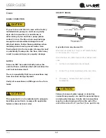
Cleaning
EXTERIOR CLEANING
Vinyl Clad (Black or White) Models
Clean surfaces with a mild detergent and warm water
solution. Do not use solvent-based or abrasive cleaners.
Use a soft sponge and rinse with clean water. Wipe with a
soft, clean towel to prevent water spotting.
Clean any glass surfaces with a non-chlorine glass
cleaner.
Stainless Models
Stainless door panels, handles and frames can discolor
when exposed to chlorine gas, pool chemicals, saltwater
or cleaners with bleach.
Keep your stainless unit looking new by cleaning with a
good quality all-in-one stainless steel cleaner and polish
monthly. For best results use Claire
®
Stainless Steel
Polish and Cleaner. Comparable products are acceptable.
Frequent cleaning will remove surface contamination that
could lead to rust. Some installations may require cleaning
weekly.
Do not clean with steel wool pads.
Do not use stainless steel cleaners or polishes on
any glass surfaces.
Clean any glass surfaces with a non-chlorine glass
cleaner.
Do not use cleaners not specifically intended for
stainless steel on stainless surfaces (this
includes glass, tile and counter cleaners).
If any surface discoloring or rusting appears, clean it
quickly with Bon-Ami
®
or Barkeepers Friend Cleanser
®
and
a nonabrasive cloth. Always clean with the grain. Always
finish with Claire
®
Stainless Steel Polish and Cleaner or
comparable product to prevent further problems.
Using abrasive pads such as ScotchBrite™ will
cause the graining in the stainless steel to
become blurred.
Rust not cleaned up promptly can penetrate the
surface of the stainless steel and complete
removal of the rust may not be possible.
Integrated Models
To clean integrated panels, use household cleaner per the
cabinet manufacturer’s recommendations.
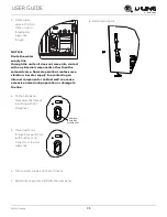
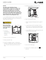
INTERIOR CLEANING
Disconnect power to the unit.
Clean the interior and all removed components using a
mild nonabrasive detergent and warm water solution
applied with a soft sponge or non-abrasive cloth.
Rinse the interior using a soft sponge and clean water.
Do not use any solvent-based or abrasive
cleaners.
These types of cleaners may transfer taste
and/or odor to the interior products and damage or
discolor the interior.
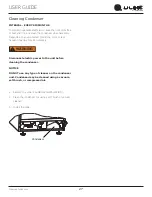
CLEAR ICE MACHINE CLEANING CYCLE
Your U-Line clear ice machine has an automatic clean
alert function. Cleaning cycles should be run as notified.
Otherwise, to maintain operational efficiency the unit
should be cleaned every three months. Depending on
water conditions, more frequent cleaning may be
necessary. If the ice machine requires more frequent
cleaning, consult a plumber to test the water quality and
recommend appropriate treatment.
CAUTION
!
Wear rubber gloves and safety goggles and/or
face shield when handling Ice Machine Cleaner.
24


