USER GUIDE
Troubleshooting Extended
MAIN CONTROL
The main control board is very robust and is rarely the
cause of system issues. It is important to fully diagnose
the board for any suspected failures before attempting
to remove the board for replacement or service. Follow
the guidelines below to fully test and diagnose the main
control.
Power Fault
If the unit does not (or seems to not) power on, follow the
flow chart below to help diagnose the issue. Before begin
-
ning it is important to first verify the unit is not simply set
to sabbath mode.
Check Voltage
At Wall Outlet
Verify Voltage At
Main Control
Voltage Input
Check Fuse F1
For Continuity
Replace
Plunger Switch
Replace Main
Board
Replace
Fuse
Replace
Power Cord
Alert Customer
Of Power Failure
Is the Plunger
Switch Operating
Properly?
Inspect
Customer UI
and Data Cable
Connect Test Display
Cycle Power And Check
For Operation
No Voltage
No Voltage
Voltage
Continuity
Operating
Not Operating
No Continuity
No
Yes
Voltage
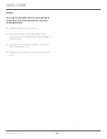
CAUTION
!
Precautions must be taken while working with
live electrical equipment. Be sure to follow
proper safety procedures while performing tests
on live systems.
PLUNGER SWITCH
A plunger switch is used to monitor door state. When the
door is closed it comes into contact with the plunger which
closes a circuit which turns the light and display off. When
the door is open the plunger moves outward and opens the
circuit. If the door is left open for longer than 5 minutes
the switch will trigger an error code and set an audible
warning.
46


