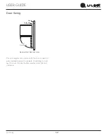
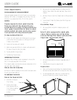
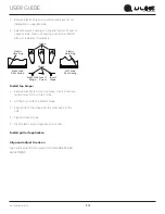
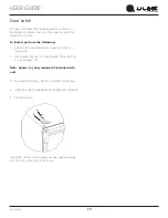
background image

USER GUIDE & SERVICE MANUAL

Model: UMCR014-SC01A

Summary of Contents for UMCR014-SC01A

Page 1: ...USER GUIDE SERVICE MANUAL Model UMCR014 SC01A ...

Page 2: ...oduct Dimensions Water Hookup General Installation Grille Installation Door Swing Door Adjust Maintenance Door Latch Cleaning Cleaning Condenser Extended Non Use Operating Instructions First Use Ice Airflow and Product Loading Service Troubleshooting Wire Diagram Product Liability Warranty Claims Parts Ordering Replacement Parts System Diagnosis Guide Compressor Specifications Troubleshooting Exte...

Page 3: ...ine RIGHT PRODUCT RIGHT PLACE RIGHT TEMPERATURE PRODUCT INFORMATION Looking for additional information on your product User Guides Spec Sheets CAD Drawings and Product Warranty information are available digitally on u line com PROPERTY DAMAGE INJURY CONCERNS In the unlikely event property damage or personal injury is suspected related to a U Line product please take the following steps 1 U Line Cu...

Page 4: ...r or moderate personal injury property or equipment damage This unit contains R600a Isobutane which is a flammable hydrocarbon It is safe for regular use Do not use sharp objects to expedite defrosting Do not service without consulting the R600a specifications section included in the User Guide Do not damage the refrigerant circuit Service must be done by factory authorized service personnel Any p...

Page 5: ...in place so children may not easily climb inside If the unit is being removed from service for disposal check and obey all federal state and local regulations regarding the disposal and recycling of refrigeration appliances and follow these steps completely 1 Remove all consumable contents from the unit 2 Unplug the electrical cord from its socket 3 Remove the door s drawer s DANGER 5 ...

Page 6: ...emperatures may reduce the unit s ability to reach low temperatures and or reduce ice production on applicable models For best performance keep the unit out of direct sunlight and away from heat generating equipment In climates where high humidity and dew points are present condensation may appear on outside surfaces This is considered normal The condensation will evaporate when the humidity drops...

Page 7: ...the unit Always keep your working area dry NOTICE Electrical installation must observe all state and local codes This unit requires connection to a grounded three prong polarized receptacle that has been placed by a qualified electrician The unit requires a grounded and polarized 115 VAC 60 Hz 15A power supply normal household current An individual properly grounded branch circuit or circuit break...

Page 8: ...REAR FRONT TOP SIDE Cutout Height 25 1 16 637 mm 18 1 2 470 mm Filler Panel Not Provided by U Line Needed to Attach Mounting Flange on Unit Toe Kick 14 1 4 362 mm Cutout Width 3 4 19 mm Minimum Flange Mounting Area 3 4 19 mm Minimum Flange Mounting Area 3 4 19 mm Minimum Flange Mounting Area Preferred location for water line and electrical outlet is in adjacent cabinet 5 8 16 mm 4 102 mm 7 178 mm ...

Page 9: ...only Do not use any plastic water supply line The line is under pressure at all times Plastic may crack or rupture with age and cause damage to your home Do not use tape or joint compound when attaching a braided flexible water supply line that includes a rubber gasket The gasket provides an adequate seal other materials could cause blockage of the valve Failure to follow recommendations and instr...

Page 10: ...l evenly Use a level to confirm the unit is level Level should be placed along top edge and side edge as shown INSTALLATION 1 Plug in the power electrical cord 2 Gently push the unit into position Be careful not to entangle the cord or water line 3 Re check the leveling from front to back and side to side Make any necessary adjustments 4 Remove interior packing material and wipe out the inside of ...

Page 11: ... touch the condenser fins The condenser fins are SHARP and can be easily damaged Removing the grille 1 Disconnect power to the unit 2 Open unit door 3 Remove the center screw 4 Remove grille by sliding grille up and pulling it toward you Installing the grille 1 Open unit door 2 Align grille with front of unit slide front tab on grille behind front of base 3 Install center screw 4 Reconnect power t...

Page 12: ...Stainless Steel 16 1 2 90 Door Swing Black White and Wood Overlay Wall Wall 90 Door Swing Integrated Stainless Steel Black and White 90 Door Swing 2175R F 2275WC Models 90 Door Swing Wall Wall 21 25 1 2 90 Door Swing 21 25 1 2 Stainless Steel Wood Overlay 2175BEV 90 Door Swing Wall Wall 90 Door Swing Stainless Steel 2175WC Models 2 1 8 Min 54 mm 1 4 Min 6 mm 2 1 8 Min 54 mm 1 4 Min 6 mm 2 1 8 Min ...

Page 13: ... hinge hardware will be removed and reinstalled on the opposite side of the cabinet Remove door latch assembly Remove door latch assembly and reinstall on opposite side of door see DOOR LATCH TO REVERSE THE DOOR Remove top hinge and door 1 Hold door to keep it from falling 2 Remove top hinge from cabinet using a Torx T 25 screwdriver to remove three screws 3 Remove door by tilting forward and lift...

Page 14: ...vot screw from top hinge invert screw and reinstall pivot screw in top hinge 2 Lift the door onto the bottom hinge 3 Align edge of the hinge with the outer edge of the unit 4 Tighten three screws 5 Insert plastic plug in opposite end of door Install grille if applicable Align and adjust the door Align and adjust the door see DOOR ALIGNMENT AND ADJUSTMENT Plastic Hole Plug Plastic Hole Plug Hinge S...

Page 15: ...ng 1 Remove the two outer most screws from the non hinge side 2 Place spacer 2 over mounting holes Place latch 1 on top of spacer 2 Note Spacer 2 only required if included with unit 3 Re install the screws but do not tighten all the way 4 Verify door latch engagement and adjust as necessary 5 Tighten screws Door latch can be used to prop door open approximately 1 2 13 mm when unit is not in use 2 ...

Page 16: ... U Line recommends discarding the ice produced during the first two to three hours of operation to avoid possible dirt or scale that may dislodge from the water line To turn the unit on or off Press the rocker switch located inside the door on the front panel or behind the grille OFF ON 16 ...

Page 17: ... s operation You may hear the compressor or fan motor the water valve or ice dropping into the ice bucket CAUTION NEVER use an ice pick knife or other sharp instrument to separate cubes Shake the ice bucket instead During periods of limited use or high ambient temperatures it is common for cubes to fuse together Gently shake the bucket to break apart cubes If not using the ice maker regularly empt...

Page 18: ...rge of an adjustment to the screw can cause the water to overflow the ice maker and can cause property damage 3 Turn the adjusting screw toward the minus sign clockwise for smaller cubes or toward the plus sign counterclockwise for larger cubes 4 Install the ice maker assembly cover ADJUSTING ICE HARVEST 1 Remove the front grille see GRILLE INSTALLATION 2 Using a flat tip screwdriver turn the adju...

Page 19: ...INTEGRATION OPERATING INSTRUCTIONS MAINTENANCE SERVICE Airflow and Product Loading NOTICE The unit requires proper airflow to perform at its highest efficiency Do not block the front grille at any time or the unit will not perform as expected Do not install the unit behind a door USER GUIDE u line com SAFETY INSTALLATION INTEGRATION OPERATING INSTRUCTIONS MAINTENANCE SERVICE Airflow and Product Lo...

Page 20: ... non chlorine glass cleaner Do not use cleaners not specifically intended for stainless steel on stainless surfaces this includes glass tile and counter cleaners If any surface discoloring or rusting appears clean it quickly with Bon Ami or Barkeepers Friend Cleanser and a nonabrasive cloth Always clean with the grain Always finish with Claire Stainless Steel Polish and Cleaner or comparable produ...

Page 21: ...d discard ice 3 Place towel or other absorbent material on bottom of ice bin 4 Fill the ice bucket half full with warm not hot water This will help the unit defrost faster 5 Place the ice bucket back into the unit on top of the towel or other absorbent material 6 Prop the door in an open position 2 in 50 mm minimum 7 After about 1 hour remove the ice bin and discard water 8 Allow the frost to melt...

Page 22: ...environmental conditions more or less frequent cleaning may be necessary WARNING Disconnect electric power to the unit before cleaning the condenser NOTICE DO NOT use any type of cleaner on the condenser unit Condenser may be cleaned using a vacuum soft brush or compressed air 1 Remove the grille See GRILLE INSTALLATION 2 Clean the condenser coil using a soft brush or vacuum cleaner 3 Install the ...

Page 23: ...or must remain open to prevent formation of mold and mildew Open door a minimum of 2 50 mm to provide the necessary ventilation WINTERIZATION If the unit will be exposed to temperatures of 40 F 5 C or less the steps above must be followed In addition P60 drain pumps in clear ice machines must be drained according to the following procedure 1 Remove the drain pump from the ice machine 2 Drain the w...

Page 24: ...dency to reflect normal appliance operating noises Listed below are common refrigeration components with a brief description of the normal operating sounds they make NOTE Your product may not contain all the components listed Compressor The compressor makes a hum or pulsing sound that may be heard when it operates Evaporator Refrigerant flowing through an evaporator may sound like boiling liquid C...

Page 25: ... setting Ambient temperature where installed Installation in direct sunlight or near a heat source The number of door drawer openings and the time the door drawer is open The time the internal light is illuminated This mainly affects product on the top rack or shelf Obstruction of front grille or condenser Product is Not Cold Enough Air temperature does not indicate product temperature See CHECKIN...

Page 26: ...IGHT BLUE WHITE DARK BLUE BLACK BROWN BLACK BROWN WHITE DARK BLUE BIN SW NO NC C WATER SW NC NO C H O L D S W N O N C C CAM 3 RPM MOTOR LIMIT SW MOLD HEATER YELLOW BLACK RED WHITE WHITE DARK BLUE BROWN YELLOW RED BROWN ORANGE BLACK BROWN BROWN W YELLOW RED Y E L L O W BROWN BLACK BROWN O R A N G E O R B L U E BLACK OR BLUE OR ALL OTHER MODELS ICEMAKER BI1215 ONLY CONTROL POWER CORD ASSEMBLY GROUND...

Page 27: ...ent of a part the servicer is authorized to replace the part in question The part that caused the damage must be returned to U Line in its entirety The part must be clearly labeled with the serial number of the unit it was removed from the date and the servicer who removed the part If the service technician determines the damage is the result of installation issues water connection drain etc the c...

Page 28: ...ashes 12 represents the production month In most cases warranty status can be verified by the production date information within the serial number Alternatively a Proof of Purchase or equivalent may submitted with the warranty claim to document warranty status We also accept the following information to verify warranty status New Construction Occupancy Documents Closing Paperwork Final Billing Rem...

Page 29: ...EPLATE 115V 80 54523 00 11 FEET 4 80 54529 00 12 FLANGE ASSEMBLY SS FC 80 54655 00 13 GRILLE W SCREWS 80 54657 00 14 HINGES W SCREWS 80 54574 00 15 ICE BUCKET 80 54611 00 16 ICEMAKER 115V R600 MANUAL 80 55669 00 17 PACKAGING 80 54612 00 18 POWER CORD EXTERNAL 80 55519 00 19 WIRE HARNESS MAIN 80 55638 12 20 WIRE ASSEMBLY CONTROL 80 55638 11 21 ROCKER SWITCH 80 55603 00 22 TRAVEL HANDLE W SCREWS 80 ...

Page 30: ...ts will be shipped at no charge after U Line confirms warranty status Please provide the model serial number part number and part description Some parts will require color or voltage information If U Line requires the return of original parts we will inform you when the parts order is taken This requirement will be noted on your packing list A prepaid shipping label will be included with the repla...

Page 31: ...e Lower than normal Warm near room temperature Hot Warm Warm Extremely cold near inlet Outlet below room temperature Lower than normal Partial Restriction Somewhat lower than normal vacuum Warm near room temperature Very hot Top passes warm Lower passes cool near room temperature due to liquid Room temperature cool or colder Extremely cold near inlet Outlet below room temperature backing up Lower ...

Page 32: ...static wrist strap that is grounded to an electrical ground or grounded water pipe Handle circuit boards carefully and avoid touching components To measure the start winding resistance measure across the C and S pins To measure the run winding resistance measure across the C and R pins Also check S to R and you should get the sum of the run and start windings To ensure the windings are not shorted...

Page 33: ...ice Bin switch inoperable closed Replace bin switch Bin arm binding Lubricate bin arm pivot points or loosen bin arm lever screw Water will not stop filling Water switch inoperable closed Replace water switch Solenoid valve inoperable Replace solenoid valve Stalled ice maker motor Replace motor Temperature control inoperable Ice maker is in continuous harvest cycle contacts 1 2 closed Replace temp...

Page 34: ... fill tube assembly Defrost drain line not in drain pan Position drain line in drain pan Crack in water line Replace water line Water leak inside unit Ice maker assembly fill cup obstructed Remove obstruction Fill ice cup and fill tube out of alignment Align fill tube and fill cup Water level too high Adjust water level Defrost drain plugged Frost Free units only Ice in drain trough Frost Free uni...

Page 35: ...ltage Voltage Drop Wiring Temperature Control Failure Water Adjustment Bin Switch Failure NO NO EVERYWHERE INTERMITTENT AT 3 00 YES NO AT 12 00 DOES THE UNIT HARVEST ICE IF THE EJECTOR BLADES ARE MOVED BY HAND OR WITH A WRENCH WHERE DO THE EJECTOR BLADES STOP Mold Heater Failure Solenoid Valve Failure Ice Motor Failure Hold Switch Failure Limit Switch Failure Binding Cam Ejector Water Switch Failu...

Page 36: ... 2 and 3 are closed Power to the condenser Power to the condenser fan Figure 1 Freeze Cycle SWITCH LIMIT orange black black black MOTOR MAKER ICE MOLD HEATER WATER SWITCH FILL C NC MOTOR FAN LOAD OVER black RELAY START COMP SWITCH OFF ON black black blue black CONTROL TEMP NC black orange 3 yellow 2 orange SWITCH BIN red NO 1 C NO brown black white C SWITCH HOLD VALVE WATER ground UL183 4 36 ...

Page 37: ... power goes through bin arm switch to the ice maker motor If bin arm is up the ice maker will not harvest Figure 2 Harvest 1 Cycle Hold Switch in Normal Position SWITCH LIMIT orange black black black MOTOR MAKER ICE MOLD HEATER WATER SWITCH FILL C NC MOTOR FAN LOAD OVER black RELAY START COMP SWITCH OFF ON black black blue black CONTROL TEMP NC black orange 3 yellow 2 orange SWITCH BIN red NO 1 C ...

Page 38: ...er motor and mold heater Ejector blades stall on ice and ice maker motor pulsates until mold heater warms and ice releases Figure 3 Harvest 2 Cycle Hold Switch in Switched Position SWITCH LIMIT orange black black black MOTOR MAKER ICE MOLD HEATER WATER SWITCH FILL C NC MOTOR FAN LOAD OVER black RELAY START COMP SWITCH OFF ON black black blue black CONTROL TEMP NC black orange 3 yellow 2 orange SWI...

Page 39: ...CT CYCLE Ejector blades push ice into bucket and stop at 12 00 position Temperature control terminals 2 and 3 have closed during harvest cycle Next freeze cycle begins with power to the compressor and condenser fan SWITCH LIMIT orange black black black MOTOR MAKER ICE MOLD HEATER WATER SWITCH FILL C NC MOTOR FAN LOAD OVER black RELAY START COMP SWITCH OFF ON black black blue black CONTROL TEMP NC ...

Page 40: ...erature After ice is sensed in the mold the 2 3 contacts open stopping the compressor and the 2 1 contacts are closed starting the ice maker motor The 2 3 contacts close 2 1 contacts open before the end of the ice harvest cycle The hold switch prevents power going back to the compressor This prepares the control for the next cycle Figure 5 Temperature Controls Manual Defrost Ice Makers YELLOW WIRE...

Page 41: ...tch Open temperature 104 F Close temperature 83 F The function of this switch is to open in the event of an overheating condition This bi metal thermostat is normally closed and does not initiate the ice harvest cycle The ice harvest cycle is initiated by a double throw single pole temperature located remotely from the ice maker assembly Figure 6 Limit Switch 28 12 3 00 183 10 41 ...

Page 42: ...et tube 5 Remove front cover 3 6 Advance the ejector blade to the 3 o clock position by turning the 5 16 hex head on the small brass gear counterclockwise 4 7 Remove three screws from wall of freezer housing 5 8 Remove ice maker assembly 9 Place new ice maker assembly into position and secure with three screws 5 10 Reconnect wire harness at plug 11 Insert control capillary tube into ice maker sens...

Page 43: ...m evaporator shelf 11 Apply 1 4 layer of fresh alumilastic to heater side of new ice maker 12 Replace parts in reverse order of removal 13 Reconnect all wires 14 Insert capillary tube into ice maker sensing tube 15 Insert water inlet tube 16 Apply permagum to all exit holes Mount back panel 17 Mount the back panel 18 Plug in unit and test 220 Volt Conversion List All models listed in this manual a...

Page 44: ...o defrost unit remove ice bucket Turn unit off Use toweling inside to absorb water as it melts down This will help prevent water from getting onto customer s floor The defrost duration is dependent upon usage or climate Typically defrosting is needed approximately every 3 6 weeks and or when 1 4 or more of frost is present whichever comes first 44 ...

Page 45: ...od or other natural disasters The product must be installed operated and maintained in accordance with your product s User Guide The remedies described above for each warranty are the only ones that U Line will provide either under these warranties or under any warranty arising by operation of law U Line will not be responsible for any consequential or incidental damages arising from the breach of...

Reviews: