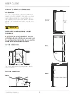
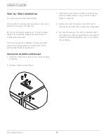
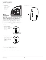
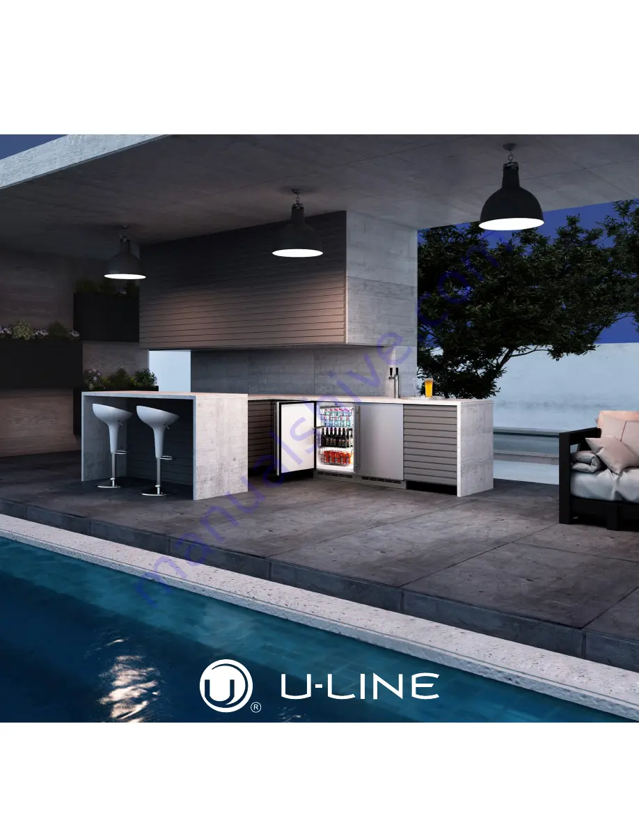
background image

USER GUIDE & SERVICE MANUAL

Model: UOCP115-SS01B

Summary of Contents for UOCL115-SS01B

Page 1: ...USER GUIDE SERVICE MANUAL Model UOCP115 SS01B ...

Page 2: ...ain Anti Tip Bracket General Installation Grille Installation Door Swing Door Adjust Maintenance Cleaning Cleaning Condenser Extended Non Use Operating Instructions First Use Control Operation Ice Airflow and Product Loading Service Troubleshooting Wire Diagram Product Liability Warranty Claims Parts Ordering Replacement Parts R600a Specifications System Diagnosis Guide Compressor Specifications T...

Page 3: ...GHT PRODUCT RIGHT PLACE RIGHT TEMPERATURE PRODUCT INFORMATION Looking for additional information on your product User Guides Spec Sheets CAD Drawings and Product Warranty information are available digitally on u line com PROPERTY DAMAGE INJURY CONCERNS In the unlikely event property damage or personal injury is suspected related to a U Line product please take the following steps 1 U Line Customer...

Page 4: ...moderate personal injury property or equipment damage This unit contains R600a Isobutane which is a flammable hydrocarbon It is safe for regular use Do not use sharp objects to expedite defrosting Do not service without consulting the R600a specifications section included in the User Guide Do not damage the refrigerant circuit Service must be done by factory authorized service personnel Any parts ...

Page 5: ...ce so children may not easily climb inside If the unit is being removed from service for disposal check and obey all federal state and local regulations regarding the disposal and recycling of refrigeration appliances and follow these steps completely 1 Remove all consumable contents from the unit 2 Unplug the electrical cord from its socket 3 Remove the door s drawer s DANGER 5 ...

Page 6: ...duce ice production on applicable models For best performance keep the unit out of direct sunlight and away from heat generating equipment In climates where high humidity and dew points are present condensation may appear on outside surfaces This is considered normal The condensation will evaporate when the humidity drops CAUTION Damages caused by ambient temperatures of 40 F 4 C or below are not ...

Page 7: ...nit Always keep your working area dry NOTICE Electrical installation must observe all state and local codes This unit requires connection to a grounded three prong polarized receptacle that has been placed by a qualified electrician The unit requires a grounded and polarized 115 VAC 60 Hz 15A power supply normal household current An individual properly grounded branch circuit or circuit breaker is...

Page 8: ...OT be installed behind a closed cabinet door If you would like to align the face of the unit with other adjacent cabinet doors you may need to alter the wall just behind the drain connection on the unit to accommodate the drain CUTOUT DIMENSIONS 15 cutout width sufficient if door protrudes beyond adjacent cabinetry PRODUCT DIMENSIONS REAR 1 ȟȭ 38 mm 7 178 mm 15 ȟȯ 387 mm 34 ȟȯ 870 mm to 35 ȟȯ 889 ...

Page 9: ...ccording to each unit s electrical specifications requirements Side by Side Installation with Bracket 1 Slide both units out so screws on top of units are easily accessible 2 Remove screws as shown below 3 Place bracket over holes and attach to unit with two screws removed in step 2 using a T 25 Torx driver Tighten screws fully 4 Gently push units into position Be careful not to entangle the elect...

Page 10: ...tion WARNING Connect to potable water supply only CAUTION Review obey and understand the local plumbing codes before you install your unit Connect to the cold water supply The water pressure should be between 20 and 120 psi 138 and 827 kPa The water line MUST have a shut off valve on the supply line CAUTION Do not use any plastic water supply line The line is under pressure at all times Plastic ma...

Page 11: ...s some vibration A water supply line contacting an internal component or cabinet wall can cause excessive noise during operation or damage to the line 4 On the back panel break away filler feature in bushing with flat screwdriver 5 Thread water line through back panel hole with bushing and connect to cold water supply line 6 Turn on water supply and check for leaks 7 Reinstall back panel and grill...

Page 12: ...he unit Unit has a solid base that will not allow the unit to drain below itself There is a possibility that hose connections may have loosened during shipment Verify all connections and fittings are free from leaks This equipment is to be installed with adequate backflow protection to comply with applicable federal state and local codes Model numbers including CL or NB do not include a factory in...

Page 13: ...alled U Line P60 drain pump If you need to install a P60 drain pump into your unit see DRAIN PUMP section in the User Manual See below for typical installations requiring a drain pump FACTORY INSTALLED DRAIN PUMP NOTICE Cold Water Hot Water Waste Waste Shut Off Valve Stand Pipe P60 Pump Required Air Gap Optional Hook Up Cold Water Hot Water Waste Shut Off Valve Disposal Assembly P60 Pump Required Wa...

Page 14: ...holes and attach to unit with two screws removed in step 2 using a T 25 Torx driver Tighten screws fully 4 Gently push unit into position Be careful not to entangle the electrical cord or water line if applicable 5 Check to be sure the unit is level from front to back and side to side Make any necessary adjustments The unit s top surface should be approximately 1 8 3 mm below the countertop 6 Secu...

Page 15: ...ning s rear height Shorten the unit height in the front by adjusting the front legs This allows the unit to be gently tipped into the opening Readjust the front legs to level the unit after it is correctly positioned in the opening INSTALLATION 1 Plug in the power electrical cord 2 Gently push the unit into position Be careful not to entangle the cord or water and drain lines if applicable 3 Re ch...

Page 16: ... the grille must be installed Removing the grille 1 Disconnect power to the unit 2 Slightly loosen three screws on bottom hinge 3 Remove two grille screws 4 Slide grille to the left and remove Installing the grille 1 Align cabinet and grille holes and secure but do not over tighten grille screws 3 2 Tighten three hinge screws 4 3 Connect power to unit WARNING 3 2 16 ...

Page 17: ...nits have a zero clearance for the door to open 90 when installed adjacent to cabinets Stainless Steel models require 2 1 8 54 mm door clearance to accommodate the handle if installed next to a wall Wall 90 Door Swing 2 1 8 Min 54 mm 17 ...

Page 18: ...m top of unit 2 Loosen do not remove top and bottom hinge screws using a Torx T 25 screwdriver on the top and a 1 4 socket on the bottom 3 Align door squarely with cabinet 4 Make sure gasket is firmly in contact with cabinet all the way around the door no gaps 5 Tighten bottom hinge screws 6 Tighten top hinge screws and replace hinge cover REVERSING THE DOOR Location of the unit may make it desira...

Page 19: ...ng outward exposing the gasket channel 3 Remove the 3 pieces of gasket channel filler and reinstall on the opposite end of door 4 Install gasket into channel beginning at one corner and pressing in firmly 5 Press down on middle horizontal portion of gasket until it adheres to the door surface Install top hinge and door 1 Remove pivot screw from hinge flip hinge over and install the pivot screw in ...

Page 20: ...he ice produced during the first two to three hours of operation to avoid possible dirt or scale that may dislodge from the water line When plugged in the unit will begin operating under the factory default settings If the unit was turned off during installation simply press and the unit will immediately switch on To turn the unit off press and release 20 ...

Page 21: ...ark and remain so until user resets mode unit continues to operate Disable Sabbath Mode Press and release Display and interior light return to normal operation Silent Mode ice production suspended for 3 hours Hold and Display will countdown the hours 3H 2H 1H Clean Mode See Cleaning section Showroom Mode Hold and for 5 seconds The ºF ºC symbol will flash Display will be lit and interior light will...

Page 22: ...together as a slab increases A bridge thicker than 1 8 3 2 mm may cause cubes to overfill the ice bucket 32 ice cubes are formed on a 4 x 8 slab during each cycle Each cycle takes approximately 15 20 minutes at the default cube thickness 0 Your clear ice machine is preset to produce ice between the optimal dimensions illustrated below Ice thickness adjustments are made using the control panel as f...

Page 23: ...ading Airflow and Product Loading NOTICE The unit requires proper airflow to perform at its highest efficiency Do not block the front grille at any time or the unit will not perform as expected Do not install the unit behind a door 23 ...

Page 24: ...d appropriate treatment Wear rubber gloves and safety goggles and or face shield when handling Ice Machine Cleaner Clean surfaces with a mild detergent and warm water solution Do not use solvent based or abrasive cleaners Use a soft sponge and rinse with clean water Wipe with a soft clean towel to prevent water spotting Clean any glass surfaces with a non chlorine glass cleaner EXTERIOR CLEANING V...

Page 25: ...g for 5 seconds 9 When water begins flowing over the evaporator approximately 3 minutes pour 1 2 oz of Clear Ice Machine Cleaner into the water trough The cleaning process will last approximately 45 minutes 10 Dilute 1 tablespoon bleach in 1 gallon of warm water Apply this solution to the entire inside of the storage area Then rinse thoroughly with water The unit will resume operation approximatel...

Page 26: ...nmental conditions more or less frequent cleaning may be necessary WARNING Disconnect electric power to the unit before cleaning the condenser NOTICE DO NOT use any type of cleaner on the condenser unit Condenser may be cleaned using a vacuum soft brush or compressed air 1 Remove the grille See GRILLE INSTALLATION 2 Clean the condenser coil using a soft brush or vacuum cleaner 3 Install the grille...

Page 27: ...t remain open to prevent formation of mold and mildew Open door a minimum of 2 50 mm to provide the necessary ventilation WINTERIZATION If the unit will be exposed to temperatures of 40 F 5 C or less the steps above must be followed In addition P60 drain pumps in clear ice machines must be drained according to the following procedure 1 Remove the drain pump from the ice machine 2 Drain the water i...

Page 28: ...king components Despite this technology your model may make sounds that are unfamiliar Normal operating sounds may be more noticeable because of the unit s environment Hard surfaces such as cabinets wood vinyl or tiled floors and paneled walls have a tendency to reflect normal appliance operating noises Listed below are common refrigeration components with a brief description of the normal operati...

Page 29: ...LUE WHITE DARK BLUE BLACK BROWN BLACK BROWN WHITE DARK BLUE BIN SW NO NC C WATER SW NC NO C H O L D S W N O N C C CAM 3 RPM MOTOR LIMIT SW MOLD HEATER YELLOW BLACK RED WHITE WHITE DARK BLUE BROWN YELLOW RED BROWN ORANGE BLACK BROWN BROWN W YELLOW RED Y E L L O W BROWN BLACK BROWN O R A N G E O R B L U E BLACK OR BLUE OR ALL OTHER MODELS ICEMAKER BI1215 ONLY CONTROL POWER CORD ASSEMBLY GROUND GREEN...

Page 30: ... in question The part that caused the damage must be returned to U Line in its entirety The part must be clearly labeled with the serial number of the unit it was removed from the date and the servicer who removed the part If the service technician determines the damage is the result of installation issues water connection drain etc the consumer would be notified and the issues shall be resolved a...

Page 31: ...or warranty labor Units must be registered prior to warranty submittal Customers may register at www U Line com A proof of purchase is required We also accept the following information to update warranty New construction occupancy documents Closing paperwork Final billing Remodel Warranty parts will be shipped at no charge after U Line confirms warranty status Please provide the model serial numbe...

Page 32: ...54354 00 18 GASKET DOOR 80 54235 02 19 GRILLE ASSEMBLY 15 80 55609 02 20 HI TEMP THERMISTOR 80 54070 00 21 HINGE ASSEMBLY CHROME 80 55418 01 22 ICE SCOOP CLR 80 54080 00 23 LED LIGHT STRIP AND COVER ASSY 80 54000 00 24 LEG LEVELERS 4 80 54019 00 25 MAGNET W SCREWS 2 80 54250 00 26 MAIN BOARD 80 55398 00 27 PACKAGING 80 54238 00 28 POWER CORD EXTERNAL 80 55519 00 29 PREFORMED DISPERSION TUBE 80 541...

Page 33: ...rranty status Please provide the model serial number part number and part description Some parts will require color or voltage information If U Line requires the return of original parts we will inform you when the parts order is taken This requirement will be noted on your packing list A prepaid shipping label will be emailed to you Please enclose a copy of the parts packing list and be sure the ...

Page 34: ...must observe all federal state and local laws regarding refrigerants Gloves and Eye Protection must be used R 600a is considered non toxic but is flammable when mixed with air Keep a dry powder type fire extinguisher in the work area R 600a is heavier than air do not allow any leakage migration to low areas such as basements and stairs Never use a torch on a fully charged refrigeration system Neve...

Page 35: ... pump and recovery equipment should be at least 10 feet from the work area It is recommended that a simple LPG gas detector is on site during service Ensure that all R 600a is removed from the system prior to brazing any part of the sealed system Only a clean dry leak free system should be charged with R 600a R 600A SPECIFICATIONS LABELING R 600a equipped products are labeled both the unit and the...

Page 36: ... is left within the system prior to repair simple venting is not sufficient Evacuate and charge with dry nitrogen for leak checks Repair leaks or replace system parts as required When re brazing the system must be purged with dry nitrogen and at least one access point open to the atmosphere When re brazing proper ventilation is required along with constant monitoring for the presence of R600a refr...

Page 37: ...all a Schrader Type access port on the compressor process stub Evacuate the system to 100 microns prior to charging Weigh in the R 600a charge using a refrigerant scale run compressor an extra two minutes to clear the charging hoses Seal the Schrader Type access port a proper cap and seal must be used to close the system SUMMARY Safely handling R 600a requires proper procedures and training R 600a...

Page 38: ...re Hot Warm Warm Extremely cold near inlet Outlet below room temperature Lower than normal Partial Restriction Somewhat lower than normal vacuum Warm near room temperature Very hot Top passes warm Lower passes cool near room temperature due to liquid Room temperature cool or colder Extremely cold near inlet Outlet below room temperature backing up Lower than normal Complete Restriction In deep vac...

Page 39: ...wearing an anti static wrist strap that is grounded to an electrical ground or grounded water pipe Handle circuit boards carefully and avoid touching components To measure the start winding resistance measure across the C and S pins To measure the run winding resistance measure across the C and R pins Also check S to R and you should get the sum of the run and start windings To ensure the windings...

Page 40: ...nal help is required please contact the U Line Corp Customer Care Facility at 1 414 354 0300 for assistance NORMAL OPERATING SOUNDS All models incorporate rigid foam insulated cabinets to provide high thermal efficiency and maximum sound reduction for its internal working components Despite this technology your model may make sounds that are unfamiliar Normal operating sounds may be more noticeabl...

Page 41: ...Unplug unit wait 5 seconds plug back in If main board does not beep check for 120V at black and white cables on power cord No Interior Light Light may be set to OFF Check LED strip for power Defective door switch Use component testing in service mode and test light circuit manually test door switch Condensation on exterior of unit Is unit exposed to high humidity or high ambient temps Moisture wil...

Page 42: ...ng for water P1 Pump circuit open Ice Level Issues See APPENDIX on following pages Relay DC Outputs One of the primary functions of the main control is to operate the multiple relay and DC outputs during each cycle Verify proper operation of these relays using the following procedure 1 Enter Relay Toggle through the service menu NOTICE Frequently toggling the compressor relay could force the compr...

Page 43: ...ved Filters available at u line com are able to treat TDS up to 600 b If TDS is acceptable unit must be cleaned and any leakage addressed with a seal kit U Line service part 80 55371 13 Area in Front of Sensors Condenser Side is Wet Check connection from bin to drain No Water is Evident 1 Power cycle to reset error 2 Check sensors to ensure there is a gap between sensors and pan as shown 3 If erro...

Page 44: ...eneral cleaning has not been performed A single cleaning may not resolve this condition c If customer has unit connected to a water softener have them consult a plumber to disconnect from the softener d Check compressor operation If unit is not cooling or compressor is not operating diagnose and fix system problem If unit is cooling check auger for rotation If not rotating check the motor and elec...

Page 45: ...display This mode can be canceled by pressing and releasing The mode will automatically be changed back to ON after three hours SHOWROOM MODE This mode is designed to show units in a display environment When in this mode the only functions will be the control and cabinet lights The compressor fans etc will not operate To enter exit this mode hold the light key and the power key for 5 seconds The d...

Page 46: ...riod frequency that data is output to diagnostics port 27 Factory test mode 0 Off 1 On 28 Compressor RPM 29 Freeze time adjust Model 54 only 30 Harvest time adjust Model 54 only 31 Low temp alarm limit Model 55 only 32 High temp alarm limit Model 55 only 1 THERMISTOR 1 BIN This shows the pure thermistor reading with no off sets taken into account 2 Does not apply to this model 3 Does not apply to ...

Page 47: ...y 23 ACTIVATE DEFROST HARVEST Press and hold for 3 seconds to activate 24 FACTORY DEFAULTS Press and hold for 3 seconds to restore all values to factory defaults 25 MAIN SOFTWARE 26 Does not apply to this model 27 FACTORY TEST MODEL 0 Off 1 On 28 COMPRESSOR RPM 29 FREEZE TIME ADJUST MODEL 54 ONLY 30 HARVEST TIME ADJUST MODEL 54 ONLY 31 LOW TEMP ALARM LIMIT MODEL 55 ONLY 32 HIGH TEMP ALARM LIMIT MO...

Page 48: ...HWC524 1A 39 HWC524 2A 40 HWC336 1A 41 HBD324 1A 42 HBD324 2A 43 HBD524 1A 44 HBD524 2A 45 HWD324 2A 46 HWD324 1A 47 HWD524 2A 48 HWD524 1A 49 HRF124 2A 50 HRF124 1A 51 HRI124 2A 52 HRI124 1A 53 Nugget 1 Class 54 Grid Ice 55 Medical Refrigerator 56 Full size 57 Nugget 3 Class PROGRAMMING THE UNIT TO CORRECT MODEL NUMBER 1 Disconnect the unit from power source 2 Push and hold the U Line button 3 Wh...

Page 49: ...t 2 Evap Fan Cond Fan 22 RE336 1A Compressor Top Left Valve Bot Right Valve Light 1 Light 2 Evap Fan Evap Fan 2 Cond Fan 23 RE515 1A Compressor Light 1 Light 2 Evap Fan Cond Fan 25 RE524 1A Compressor Light 1 Light 2 Evap Fan Cond Fan 27 RE324 1A Compressor Light 1 Light 2 Evap Fan Cond Fan 29 KR524 1A Compressor Light 1 Light 2 Evap Fan Cond Fan 32 WC315 1A Compressor Light 1 Light 2 Evap Fan Con...

Page 50: ...ne Thermistor If the zone thermistor in the unit fails the unit will continue to cool in a backup mode Self Preservation Mode to preserve the integrity of the contents The unit will otherwise operate normally USER GUIDE u line com Thermistor Thermistors are used for various temperature readings Thermistors provide reliable temperature readings using a resistance which varies based on surrounding t...

Page 51: ... improper use maintenance installation service repair acts of God fire flood or other natural disasters The product must be installed operated and maintained in accordance with your product s User Guide The remedies described above for each warranty are the only ones that U Line will provide either under these warranties or under any warranty arising by operation of law U Line will not be responsi...

Reviews: