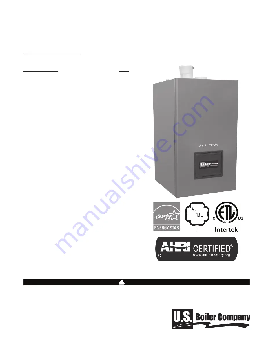
background image

110327-02 - 7/20

ALTA

• Combi Boiler/Water Heater

• Condensing

• Direct Vent

• Gas Fired

Model: ALTAC-136

  WARNING


This boiler must only be installed, serviced, or repaired by a qualified heating installer or service technician. 

Improper installation, adjustment, alteration, service or maintenance can cause severe personal injury, death, 

or substantial property damage. For assistance or additional information, consult a qualified installer, service 

agency, or the gas supplier. Read these instruction carefully before installing.

!

Installation, Operating and Service Instructions for

Manual Contents                                                  Page

1.  Installer Read Before Proceeding  . . . . . . . . . . .3
2.    Homeowner Read Before Proceeding . . . . . . . .4
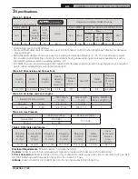
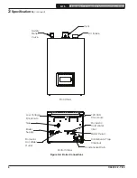
3.    Specifications  . . . . . . . . . . . . . . . . . . . . . . . . . . .5
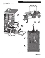
4.   How It Works  . . . . . . . . . . . . . . . . . . . . . . . . . . . .7
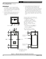
5.   Locating Boiler  . . . . . . . . . . . . . . . . . . . . . . . . . .9
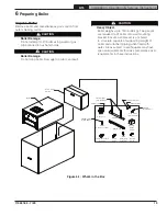
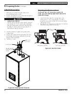
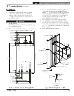
6.   Preparing Boiler  . . . . . . . . . . . . . . . . . . . . . . . .13
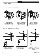
7.   General Venting  . . . . . . . . . . . . . . . . . . . . . . . . .16
8.    Sidewall Direct Venting . . . . . . . . . . . . . . . . . . .23
9.   Vertical Direct Venting   . . . . . . . . . . . . . . . . . . .29
10.  Heating System Piping  . . . . . . . . . . . . . . . . . . .35
11.  Domestic Water Piping  . . . . . . . . . . . . . . . . . . .38
12.  Gas Piping . . . . . . . . . . . . . . . . . . . . . . . . . . . . .41
13.  Field Wiring   . . . . . . . . . . . . . . . . . . . . . . . . . . . .42
14.  Condensate Disposal  . . . . . . . . . . . . . . . . . . . .45
15.  Start-up and Checkout    . . . . . . . . . . . . . . . . . .46
16.  Operation  . . . . . . . . . . . . . . . . . . . . . . . . . . . . . .52
17.   Before Leaving Jobsite   . . . . . . . . . . . . . . . . . .64
18.  Service and Maintenance  . . . . . . . . . . . . . . . . .65
19.  Troubleshooting   . . . . . . . . . . . . . . . . . . . . . . . .69
20.  Internal Wiring Diagrams   . . . . . . . . . . . . . . . . .83
21.   Service Parts . . . . . . . . . . . . . . . . . . . . . . . . . . .86
Appendix
  A. Combination Refrigeration/Heating System  . .92
  B. Water Quality and Boiler Additives  . . . . . . . . .93
  C. Special Requirements In Massachusetts  . . . .94
  D. Code Required Text  . . . . . . . . . . . . . . . . . . . . . .96

TO THE INSTALLER: 

Affix these instructions adjacent to boiler.

Provide model number and serial number when 

seeking information and support.

TO THE HOMEOWNER: 

Retain these instructions for future reference.

Contact heating installer or technician for all issues

and support.

Summary of Contents for ALTA ALTAC-136

Page 1: ...ons 5 4 How It Works 7 5 Locating Boiler 9 6 Preparing Boiler 13 7 General Venting 16 8 Sidewall Direct Venting 23 9 Vertical Direct Venting 29 10 Heating System Piping 35 11 Domestic Water Piping 38...

Page 2: ...rious injury DANGER Explosion Hazard DO NOT store or use gasoline or other flammable vapors or liquids in the vicinity of this or any other appliance If you smell gas vapors DO NOT try to operate any...

Page 3: ...en oxides and or other toxic or harmful substances that can be hazardous to health and life and that are known to the State of California to cause cancer birth defects and other reproductive harm Do n...

Page 4: ...air flow into or around boiler Insufficient air may cause the boiler to produce carbon monoxide or start a fire BURN HOT Water temperature over 125 F 52 C can cause severe burns instantly or death fro...

Page 5: ...Space Heating Water sweat in Domestic Water sweat in Gas NPT Relief Valve NPT Maximum Allowable Working Pressure psi kPa 16 3 413 17 8 453 29 8 757 1 1 4 3 4 1 2 3 4 50 345 Table 3 2 Dimensions and Co...

Page 6: ...6 Boiler Connections 3 Specifications continued Safety Relief Valve Vent Air Intake Front View 120 VAC Knockouts Low Voltage Knockouts Domestic Cold Water Inlet Boiler Return Condensate Trap Cleanout...

Page 7: ...ition LCD display turns red and fault condition is displayed 11 Flue temperature sensor Used to monitor flue gas exiting boiler Boiler control will alarm reduce boiler firing rate and shut down boiler...

Page 8: ...8 ALTA Installation Operating Service Instructions 110327 02 7 20 4 How It Works continued Figure 4 1 How it works 1 2 4 15 7 8 3 18 12 9 17 13 20 21 22 19 16 11 14 10...

Page 9: ...Manufacturer will not be held responsible for water damage resulting from this appliance or any of its components 5 Check for and remove any combustible materials gasoline or other flammable liquids...

Page 10: ...ric Vent exhaust 1 4 6mm Concentric Vent or Air Intake Piping 0 Hot Water Piping 1 4 6mm Recommended Service Clearances Sides Front and Bottom 24 610mm Ventilation Air 1 Combustion air must be obtaine...

Page 11: ...minants to avoid Spray cans containing chloro fluorocarbons CFC s Permanent wave solutions Chlorinated waxes cleaners Chlorine based swimming pool chemicals Calcium chloride used for thawing Sodium ch...

Page 12: ...cal close all building doors and windows and all doors between the space in which the appliances remaining connected to the common venting system are located and other spaces of the building Turn on c...

Page 13: ...er onto wall mounting bracket Ensure wall bracket is anchored to structure capable of supporting weight of boiler and attached piping when filled with water Areas subject to earthquakes may have speci...

Page 14: ...vent connector through jacket into heat exchanger with flue gas sample port facing forward See Figure 6 2 5 Tighten 4 screws Install Vent Connector Figure 6 2 Installing Vent Connector Flue gas sampl...

Page 15: ...nters or a masonry wall For other stud spacing mount bracket to 3 4 in 19 mm plywood or horizontal 2 x 4 anchored to studs CAUTION Heavy object Do not mount boiler to a hollow wall Boiler must be anch...

Page 16: ...tion 8 for details Figure 7 3 Sidewall Concentric Termination see Section 8 for details Direct Vent Sidewall Termination Options Direct Vent Vertical Termination Options Figure 7 4 Vertical Terminatio...

Page 17: ...systems listed in Tables 7 11 or 7 16 Thoroughly inspect finished vent and air piping to ensure air tightness and compliance with provided instructions and code requirements Do not mix components from...

Page 18: ...following or equivalent may be used to join CPVC to PVC Material Standard Vent Pipe CPVC sched 40 or 80 ASTM F441 PVC sched 40 or 80 ASTM D1785 PVC DWV ASTM D2665 Vent Fittings CPVC sched 80 ASTM F439...

Page 19: ...11 Dry fit all vent and air components before cementing any joints 12 Use field supplied primer and cement appropriate for materials being joined Follow primer and cement instructions to join pipe an...

Page 20: ...h of straight run between anchors X Loop horizontal only top view Y 5 6 150mm Min 6 150mm Min 2Y 5 7 General Venting continued Figure 7 15 CPVC PVC Venting Expansion Loops Figure 7 14 PVC Venting Wall...

Page 21: ...ngths of elbows and fittings 5 Only cut polypropylene vent pipe as permitted by vent manufacturer and in accordance with their instructions Ensure cut end is square and deburred prior to assembly 6 Bo...

Page 22: ...PF LB or 4PF LB Increaser 2 in 60 mm to 3 in 80 mm 2PPS X3L ISIA0203 2PF 2I3 PF LB locking band PVC to PP Adapter 2 in 60 mm 2PPS ADL ISAGL0202 adapter IAFC02 clamp N A Table 7 17 Listed Polypropylene...

Page 23: ...as stones or balls or subject to buildup of leaves or dirt 4 Maintain clearances to vent terminal per Figure 8 1 A Minimum 12 in 305 mm from any door window or other gravity air inlet B Minimum 3 ft 9...

Page 24: ...24 ALTA Installation Operating Service Instructions 110327 02 7 20 8 Sidewall Direct Venting continued Figure 8 1 Vent Terminal Clearances Air Terminal not Shown for Clarity...

Page 25: ...f venting with polypropylene i Use UV resistant or UV stabilized components for all exterior pipe and fittings ii Remove gasket from terminal fitting to install screen 6 Brace exterior vertical runs o...

Page 26: ...igure 8 8 Low Profile Terminal Grade or Snow line From boiler vent connection Possible Orientations 12 305mm Min To boiler air connection Grade o Snow lin v Possible Orientations To boiler air connect...

Page 27: ...terminal can be shortened Follow terminal manufacturer s instructions and Figure 8 12 WARNING Asphyxiation Hazard Ensure rain cap is installed before operating boiler Operation without rain cap instal...

Page 28: ...n each female end of vent pipe or fitting Failure to make proper joint connections could cause products of combustion and or carbon monoxide to enter the building resulting in severe personal injury d...

Page 29: ...arrangement with vertical vent and sidewall air intake is permitted See Figure 9 5 9Vertical Direct Venting WARNING Asphyxiation Hazard Follow these instructions when determining vent terminal locati...

Page 30: ...Fittings DuraVent PolyPro Centrotherm InnoFlue Selkirk PolyFlue UV resistant single wall pipe 2PPS BG screen UV stabilized end pipe IASPP02 screen UV resistant pipe 2PF HVST screen Figure 9 5 Alterna...

Page 31: ...igure 9 7 for assembly Figure 9 6 CPVC PVC Concentric Terminal 9Vertical Direct Venting continued From boiler vent connection To boiler air connection 12 305mm Min USA 18 460mm Min Canada 24 610mm Max...

Page 32: ...t PVC adapter and install electrical conduit locknut to secure Seal all joints with RTV silicone B DuraVent InstallPolyProlowerB ventadapter in base of tee C Centrotherm Install cap in base of tee Rou...

Page 33: ...dapter See Text Flex Male Adapter 10 3 1m 24 610mm Min 12 305mm Min Boiler Notes 1 All B Vent joints must be sealed with RTV 2 Seal the Flex Male Adapter to the inside of the lower B Vent Adapter with...

Page 34: ...t Venting continued Table 9 15 Polypropylene Masonry Chimney Chase Components DuraVent PolyPro Centrotherm InnoFlue Selkirk PolyFlue 2PPS FKC chimney kit 2PPS FLEX flex length IFCK02 chimney kit with...

Page 35: ...isted in Clinical Toxicology of Commercial Products 5th edition 10 Heating System Piping 2 WARNING Burn Hazard Safety relief valve discharge piping must be piped near floor to eliminate potential of s...

Page 36: ...A Protection of this boiler against low water and or inadequate flow is provided by UL353 certified flow switch built into boiler B Thisisawatertubeboilerandthisflowswitch is therefore only effective...

Page 37: ...System Pump To System Optional Zone Valve Controlled System System Zone Valves System Supply 1 1 4 sweat NOTICE Domestic water piping omitted for clarity NOTICE Installer is responsible for piping co...

Page 38: ...iter If DHW draw rate is in excess of rating in Table 3 1 temperature of hot water may be too low for comfortable use Internal 6 GPM 23 L min flow limiter is factory installed but an additional flow l...

Page 39: ...nstallation CAUTION Component Damage Excessive heat from soldering could damage gaskets at connection between DHW adapters and boiler Solder connections to DHW adapters before installing gaskets A Col...

Page 40: ...ve Buffer Tank 2 6 Gal optional Drain Valve ASSE 1070 Listed Anti Scald Valve required Cold Water Supply Recirc Temp Sensor P N 108703 01 Expansion Tank Req d if cold water supply line has check valve...

Page 41: ...223 1 National Fuel Gas Code and or CAN CSA B149 1 Natural Gas and Propane Installation code Figure 12 1 shows typical gas piping and connection to boiler A Use thread compound compatible with liquefi...

Page 42: ...a UL 353 listed high water temperature limit function This limit provides boiler shutdown in event boiler water temperature exceeds set point of control Certain local codes require an additional wate...

Page 43: ...t Heat T Stat 24VAC heating thermostat C 24V Common Aux T Stat 24VAC heating thermostat R 24V Hot Aux T Stat 24VAC heating thermostat W Energized on Call for Heat External Limit Field supplied safety...

Page 44: ...ectrical noise such as transformers power lines and fluorescent lighting v Wire sensor to boiler using minimum 22 AWG wire vi Where electrical noise sources cannot be avoided wire sensor using 2 condu...

Page 45: ...P N 101897 01 is available from manufacturer B Do not route or terminate condensate drain line piping through an area that is prone to freezing temperatures or that could be damaged by leaking condens...

Page 46: ...riate water chemistry guidelines will help extend the life of appliance by reducing effects of lime scale buildup and corrosion which could void warranty NOTICE Minimize introduction of make up water...

Page 47: ...label Gas Valve Fuel Setting Natural Gas Gas Valve Fuel Setting LP Gas Adjustment Screw Figure 15 3 Gas valve detail WARNING Asphyxiation Hazard Do not attempt to operate this boiler on LP gas without...

Page 48: ...established for first time subsequent calls for burner operation should result in a flame on first try 12 If there is a problem that appears before first try for ignition or if boiler fails to light a...

Page 49: ...tion testing is complete B Measure carbon monoxide CO level after 5 minutes of operation above 50 firing rate ThiscanbedonebyprovidingDHWdemand Ensure door is sealed before taking combustion readings...

Page 50: ...d clencher un incendie ou une explosion entra nant des dommages des blessures ou la mort A Cet appareil ne comporte pas de veilleuse Il est muni d un dispositif d allumage qui allume automatiquement...

Page 51: ...Calibration Burner On Pump s On Three Way Valve CH After burner is started a Calibration is initiated due to 1 Power Cycle 2 Periodic requirement Calibration after blower reaches calibration speed set...

Page 52: ...emand is present Visible when DHW heating demand is present Icon will flash if DHW setpoint is being adjusted Visible when burner is firing Icon adjacent to active priority Visible when DHW Comfort Mo...

Page 53: ...der Temperature Fr Firing Rate rUn Run Time Hours CYC Boiler Cycles H Hold or Warning Condition E Manual Reset Lockout Not available with local user display The STA status display code contains below...

Page 54: ...f Central Heat 2 CH2 Figure 16 7 Adjusting Parameters Menu c c Diagnostic Menu Table 16 9 Diagnostic Menu Display Description C01 Active Detailed Fault Code see Table 19 5 C02 Demand Source 1 Standby...

Page 55: ...enables adjustment by increments of 10 Press enter to accept value password only Pressing menu to exit Navigating Menus Entering password in Adjust Mode allows access shaded menus below and additional...

Page 56: ...entral Heat 2 Setpoint Desired water temperature of CH2 0 0 1 A06 A06 Fuel Gas Selection visible only after password entered Boiler is shipped from factory configured for natural gas Conversion to LP...

Page 57: ...t of installed home radiation is less than maximum output of boiler change F03 setting to limit boiler output accordingly 80 0 80 F04 F04 Central Heat 2 Max Modulation Defines highest modulation rate...

Page 58: ...supply water temperature that will provide enough heat for type radiation used to function properly Always consider type of radiation when adjusting this parameter 0 0 1 2 505 505Auxiliary Thermostat...

Page 59: ...odulation sensor and boiler is a stand alone boiler 3 Boiler Pump CH Only Off for DHW Pump runs during CH1 CH2 and CH frost protection demand and will be forced off if there is a DHW demand and DHW pr...

Page 60: ...d and Lead Lag Outdoor Reset is Enabled boiler will automatically adjust heating zone set point temperature based on outdoor reset curve On Enable calculate temperature setpoint based on outdoor tempe...

Page 61: ...etpoint and maximum modulation rates 6 Sensorless Reset Control system monitors recent firing rate and burner cycle data to infer current building heat loss Target supply water temperature is then adj...

Page 62: ...ny demands 2 High Differential Temperature Limit Control monitors temperature difference between return and supply sensors If this difference exceeds 58 F 32 C control begins to reduce blower maximum...

Page 63: ...s when periodic calibration is required and boiler is cold 10 Ignition Failure Control monitors ignition using a burner mounted flame sensor In event of an ignition failure the control retries 2 times...

Page 64: ...ed gas inlet pressure Performed combustion test Screw cap in vent adapter No errors or holds present on display Tested additional field installed controls for functionality outlined by manufacturer i...

Page 65: ...ate filter as a minimum 2 Long sleeved loose fitting clothing 3 Gloves 4 Eye Protection Dampen RCF to be removed with light water spray to prevent fibers from becoming airborne Take steps to assure ad...

Page 66: ...e following steps are not performed at the intervals specified 1 Inspect vent piping and air intake piping to verify it is free from leakage and deterioration Also verify vent and air intake terminals...

Page 67: ...range shown in Figure 18 3 WARNING Asphyxiation Hazard Do not operate boiler without condensate trap ball and ball support in place Doing so could cause products of combustion and or carbon monoxide t...

Page 68: ...on and for details on supporting pitching and terminating vent system 12 Inspect hydronic system and DHW piping A Look for leaks and repair if found If system contains antifreeze or other additives te...

Page 69: ...is on Servicing DHW demand Boiler is in Warm Weather Shutdown Status StA 14 Feature not available with local user display No Central Heat Boiler Runs 3 way valve defective Check 3 way valve replace if...

Page 70: ...lame sensor Refer to Section 18 Service and Maintenance for proper procedure to check ignitor flame sensor Check spark gap and ignitor flame sensor distance to burner Replace if necessary Relief Valve...

Page 71: ...ature overshoot if heating load is too small 7 Rate Limit Firing rate is being limited due to an abnormal condition such as High Supply water temperature High Differential Water temperature High Flue...

Page 72: ...n 5816 RPM Minimum Modulation 1016 RPM C04 Fan Speed Feedback RPM x 100 Should remain close to Fan Speed Demanded Large differences may mean there is a problem with blower C05 3 way Valve Status 0 DHW...

Page 73: ...r will restart after minimum off time of 1 minute 1 1 Urgent calibration cooling delay boiler start delay urgent calibration is present waiting for supply temperature to decrease Boiler will start aft...

Page 74: ...ycle power to initiate pump air elimination sequence Blown T5 0A Fuse supplies power to pumps Check T5 0A Fuse replace with a 5 Amp 250V Slow Blow 5x20mm if necessary Piping problem Verify boiler is p...

Page 75: ...ation temperature sensor Check header or recirculation sensor wiring correct wiring if necessary Check Header sensor Refer to Table 19 7 H14 0 10V 4 20mA Input Fault Shorted or miswired 0 10Vdc 4 20mA...

Page 76: ...re revision or is damaged Remove and reconnect BCC and cycle power If problem persists replace control or BCC E18 Invalid Application Parameters 18 0 Application parameters are not valid Normal condit...

Page 77: ...No gas insufficient gas supply pressure Verify no air in gas line Check gas supply pressure Check gas pressure down stream of valve Ignition Cable not plugged in Connect ignition harness check cable h...

Page 78: ...que salve address between 1 and 8 30 1 Sequencer slave has lost communication with Sequencer Master master header sensor failure Check boiler to boiler connection wiring Check master is powered and co...

Page 79: ...E06 1 Lockout Flue gas sensor detected temperatures in excess of 204 F 96 C or when used preferred high limit H07 E07 H07 0 Hold Return temperature higher than supply temperature E07 1 Lockout Return...

Page 80: ...ulation parameters Start Offset Recycle Limit 5 F H18 5 Warning Invalid Setpoint interpolation parameters H18 6 Hold Invalid comfort mode configuration E18 7 Lockout Selected boiler model default para...

Page 81: ...ration management did not work H26 3 Hold Emergency stop The burner had to be stopped during calibration adaption either due to high outlet DHW temperature or a blocking lockout error H27 H27 0 Hold 1...

Page 82: ...00 86 30 8056 104 40 5324 122 50 3599 140 60 2483 158 70 1748 176 80 1252 194 90 912 212 100 674 230 110 506 248 120 384 Table 19 8 Outdoor Air Temperature Sensor Temperature versus Resistance Outdoor...

Page 83: ...X1 6 X1 7 X2 3 X1 1 Chassis Ground X1 2 Ignitor Flame Rod Combustion Blower DC Conn Spark DC Tach PWM DC HT 1 X3 1 X3 2 X3 3 X3 4 V2 V2 V1 V1 X3 5 X3 6 X3 7 X3 8 Supply Sensor Return Sensor Flue Sens...

Page 84: ...ew bottom panel 3 1 2 RD BK BK YE WH WH GND Screw bottom panel L N L N L N L N 120V Line Boiler Pump System Pump Aux Pump R Heat T stat W C R W Aux T stat Ext Limit 0 10V 4 20mA Header Sensor Outdoor...

Page 85: ...requirements follow The National Electric Code NFPA 70 and or CSA C22 1 Electrical Code Do not provide over current protection greater than 15 Amperes 3 Plugs P1 P2 are shown in line on PCB s for clar...

Page 86: ...187 Grip 2D 10 32 x 1 2 in Thread Cutting Screw 3A Flue Outlet Gasket 105882 01 3B Flue Adapter 3 to 2 4 Flue Temperature Sensor 105883 01 5 Rear Target Wall Insulation 105651 01 6 Burner Door Gasket...

Page 87: ...110579 01 13 Supply Temp Sensor 106994 01 14 Pump 110580 01 15 T P Gauge 108215 01 16 Boiler Flow Switch O ring 105892 01 17 30 psi Safety Relief Valve 108680 01 18 Plate Heat Exchanger 110581 01 19...

Page 88: ...h gaskets o rings and hardware 110586 01 24A 24B 24C 24D 24E 24F 28 29 Gas Valve with gaskets o rings and hardware 110587 01 25A 25B Air Proving Switch tubing 5 16 in x 12 in long 107862 01 26A 26B 27...

Page 89: ...rts continued Key No Description Part Number 31A 31B 31C 31D 31E 31F 31G Condensate Trap 110589 01 32 Front Door 110595 01 33 Vent connector 107160 01 42 Side panel 110725 01 45 46 Wall brackets 11088...

Page 90: ...e 110590 01 35 Boiler Control 110591 01 36 BCC Contact U S Boiler Company Provide boiler serial number 37 Model Key 38 Low Voltage Connection Board 110594 01 Not Shown Fuse 5 0A 5 x 20mm 250V Slow Blo...

Page 91: ...zer Kit 101867 01 Auto Reset LWCO 105591 01 Manual Reset LWCO 108182 01 Thermostatic Mixing Valve 70 145F 108042 01 Fernox Alphi 11 108862 01 Hydronic System Corrosion and Lime scale Inhibitor 108863...

Page 92: ...Residential Hydronic Heating Installation and Design I B R Guide Water Chiller Shut off Valves Expansion Tank Circulator Shut off Valves Supply main to combined heating cooling system Return main from...

Page 93: ...if it is not safety relief valvemayopenfrequently resultinginregular additions of make up water D If an automatic fill valve is installed installation of a water meter in fill line is strongly recomm...

Page 94: ...is installed in a crawl space or an attic the hard wired carbon monoxide detector with alarm and battery back up may be installed on the next adjacent floor level b In the event that the requirements...

Page 95: ...horizontally vented gas fueled equipment does not provide the parts for venting the flue gases but identifies special venting systems the following requirements shall be satisfied by the manufacturer...

Page 96: ...ant 5 min ensuite d terminer si le coupe tirage d borde l ouverture de d charge Utiliser la flamme d une allumette ou d une chandelle ou la fum e d une cigarette d un cigare ou d une pipe 6 Une fois q...

Page 97: ...97 110327 02 7 20 ALTA Installation Operating Service Instructions SERVICE RECORD SERVICE PERFORMED DATE...

Page 98: ...98 ALTA Installation Operating Service Instructions 110327 02 7 20 SERVICE RECORD SERVICE PERFORMED DATE...

Page 99: ...99 110327 02 7 20 ALTA Installation Operating Service Instructions SERVICE RECORD SERVICE PERFORMED DATE...

Page 100: ...100 ALTA Installation Operating Service Instructions 110327 02 7 20 U S Boiler Company Inc P O Box 3020 Lancaster PA 17604 1 888 432 8887 www usboiler net...

Reviews: