25
VIII. Service Instructions
A.
General
Inspection and service should be conducted annually.
Turn off electrical power and gas supply while
conducting service or maintenance. Follow instructions
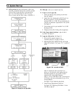
TO TURN OFF GAS TO APPLIANCE. See Figure 21.
CAUTION
Label all wires prior to disconnection when
servicing controls. Wiring errors can cause
improper and dangerous operation. Verify proper
operation after servicing.
B.
Low water cutoff
Clean probe.
1. Drain boiler to point below Tapping "L".
2. Disconnect the (3) wire multipin connector from the
control and disconnect the control's black wire from
the probe's screw terminal.
3. Remove control from probe.
4. Unscrew probe from Tapping "L".
NOTICE
Carefully remove, clean, and reinstall probe.
Platinum guard ring must not be exposed to
rough treatment, or useful life of probe may be
shortened.
5. Remove deposits from probe using diluted
phosphoric acid (H
2
PO
4
) solution, 3 parts water to 1
part phosphoric acid. Normal operation will occur
with up to 0.2 inch of contamination. If scale or
contamination exceeds 0.2 inches clean probe more
frequently.
6. Reinstall probe in Tapping "L". Mount control on
probe. Attach control's black wire to probe's screw
terminal and reconnect the (3) wire multipin
connector to the control.
C.
Water Feeder and Additional Low Water Cut-Off
Refer to manufacturer's instructions.
D.
Vent System
Inspect for obstructions, soot
accumulation, proper support, and deterioration of pipe,
fittings, and joints.
1. Clean vent terminal screens. Vent terminal must be
free of obstruction, undamaged, with screens
securely in place.
2. Vent terminal and wall thimble (if used) must be
weather-tight.
3. Vent pipe must be full round shape, and show no
damage from impact or excessive temperature.
4. Vent pipe must be supported at minimum 5 foot
intervals and must not sag.
5. All joints must be secure and watertight.
6. Condensate drain must have minimum 6 inch trap
and allow condensate to flow freely. To clean:
a. Disconnect condensate drain from drain fitting.
b. Flush condensate drain with water. Fill trap with
water.
c. Securely fasten condensate drain to drain fitting,
providing gas-tight and watertight seal.
7. If vent pipe must be disassembled for removal of
obstructions or resealing of joint, see Venting
Section.
E.
Boiler Flue Passages.
Inspect for blockage or soot
accumulation.
1. Remove Main Burners.
a. Disconnect Pilot Tubing from Gas Valve.
b. Disconnect Igniter/Sensor Wire and Pilot Ground
Wire from Ignition Module.
c. Disconnect (2) wires to Flame Roll-out Switch.
d. Remove Burner Access Panel.
e. Mark manifold with location of Main Burner
with Pilot Bracket.
f. Hold Main Burner on throat. Lift slightly to clear
orifice. Pull Main Burner from combustion
chamber. Main Burner with Pilot Bracket can
only be removed by lifting at 45° angle after
adjacent Main Burner to right is removed.
2. Disconnect Junction Box to Vestibule Wiring
Harness from Blower.
3. Remove (4) locknuts securing vent connector. See
Figure 7. Disconnect vent connector and vent pipe
from blower outlet.
4. Remove Jacket Top Panels.
5. Disconnect Silicone Tubing from Canopy. Pull
tubing through Blower Access Panel into vestibule.
6. Remove Blower Access Panel.
7. Loosen (4) carriage bolts. Remove Canopy/Blower
Assembly.
8. Remove Gasket and Flue Gas Baffles. Inspect Flue
Baffles for deterioration.
Summary of Contents for INDEPENDENCE IN3PV
Page 7: ...7 Figure 4 Steam Piping IN3PV Figure 3 Trim Installation III Steam Piping and Trim continued...
Page 29: ...29 SERVICE RECORD DATE SERVICE PERFORMED...
Page 42: ...42 SERVICE RECORD DATE SERVICE PERFORMED...
Page 43: ...43 SERVICE RECORD DATE SERVICE PERFORMED...
Page 44: ...44 U S Boiler Company Inc P O Box 3020 Lancaster PA 17604 1 888 432 8887 www usboiler net...


