121
107672-01- 7/17
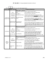
XII. Operation
F. Changing Adjustable Parameters (continued)
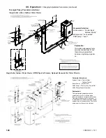
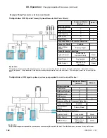
Example Pump Parameter selections (continued):
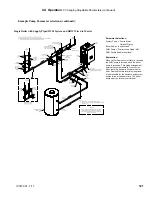
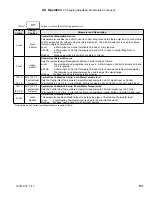
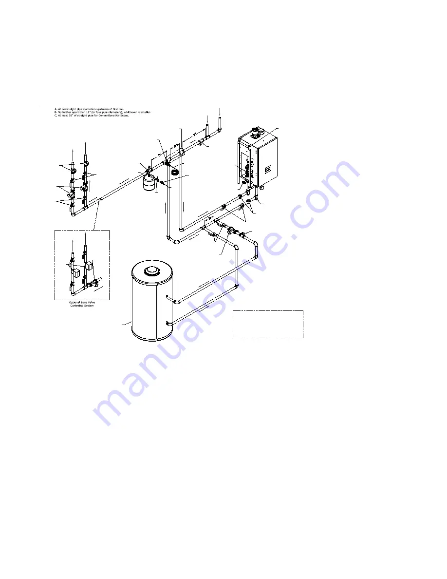
Single Boiler with Supply Piped IWH, System and DHW Wired to Master
Parameter Selections:
System Pump = “Central Heat,
Optional Priority”
Boiler Pump = “any demand”
DHW Pump = “Primary Loop Piped IWH”
DHW Priority Enable is optional
Explanation:
When call for Domestic Hot Water is received
the DHW pump is turned on and the boiler
pump is turned on. This piping arrangement
permits the system pump to run or not run
when there is a domestic hot water call for
heat. Domestic hot water priority is optional.
It is permissible for the domestic and system
pumps to run at the same time. The boiler
pump must run for every call for heat.
Flow
Check
Heating
Circulators
Optional
Full Port
Isolation
Valves
Optional
Full Port
Isolation
Valves
To
System
From
System
Air Separator
& Air Vent
Expansion Tank
Header Temperature
Sensor
(When Used)
Cold
Water
Line
Y-Strainer
(Recommended)
System
Zone
Valves
Heating
System
Circulator
To
System
Boiler
Pump
Drain
Valve
Unions
Full Port
Isolation
Valves
Tee & Plug
(Recommended For Future
Heat Exchanger Service)
Relief
Valve
Close Nipple
(Locate Header Sensor
As Close As Possible
To Downstream Tee)
Hydraulic Separator
May Be Substituted
For Tees
Fill
Valve
Backflow
Preventer
Flow
Check
Full Port
Isolation
Valves
Indirect
Circulator
Indirect Domestic
Water Heater
(IWH)
Indirect
Supply
Indirect
Return
CAUTION
It is the installer's responsibility to select boiler
piping configurations that provide the proper
flow rates and performance for the boiler and
indirect water heater.
Notes:
1. Boiler Pump Located Inside Boiler Jacket.
2. Manual Air Vent Located On Top Of Heat Exchanger.
See Figure 11.1.
Summary of Contents for K2WT-080B
Page 83: ...83 107672 01 7 17 PAGE LEFT INTENTIONALLY BLANK...
Page 89: ...89 107672 01 7 17 X Wiring continued Figure 10 5 Internal Ladder Diagram...
Page 90: ...90 107672 01 7 17 X Wiring continued...
Page 91: ...91 107672 01 7 17 Figure 10 6 Internal Wiring Connections Diagram X Wiring continued...
Page 102: ...102 107672 01 7 17 Lighting and Operating Instructions XI Start Up and Checkout continued...
Page 147: ...147 107672 01 7 17 XV Service Parts continued...
Page 151: ...151 107672 01 7 17 XV Service Parts continued...
Page 153: ...153 107672 01 7 17 XV Service Parts continued 85 86 91 95...
Page 162: ...162 107672 01 7 17...
Page 163: ...163 107672 01 7 17...
Page 164: ...164 107672 01 7 17...
Page 165: ...165 107672 01 7 17...
Page 166: ...166 107672 01 7 17...
Page 167: ...167 107672 01 7 17...

