7
107672-01- 7/17
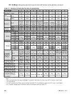
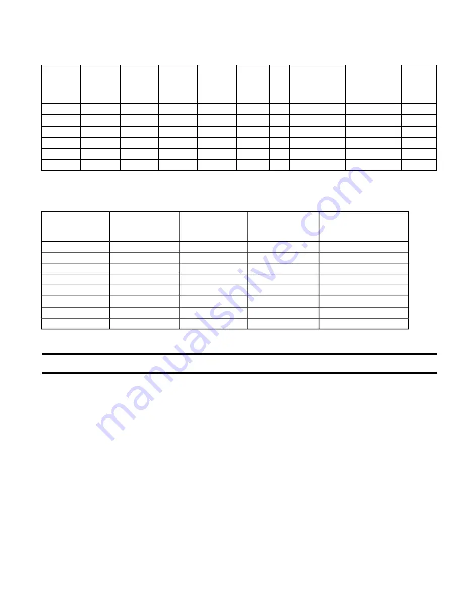
Table 2.3: Vent Lengths
Table 2.2: Specifications
Model
*
Maximum
Input
(MBH)
Minimum
Input
(MBH)
D.O.E.
Heating
Capacity
(MBH)
AHRI Net
Rating
*
(MBH)
Water
Volume
(gal.)
Dim.
“A”
Supply & Return
Connection
Size (NPT)
Gas Connection
Size (NPT)
Approx.
Net
Weight
(lb.)
K2WT-080B
80
8
74
64
0.430
17”
1”
1/2”
100
K2WT-100B
100
10
94
82
0.547
17”
1”
1/2”
102
K2WT-120B
120
12
112
97
0.650
17”
1”
1/2”
105
K2WT-150B
150
15
142
123
0.956
21”
1”
1/2”
119
K2WT-180B
180
18
169
147
0.956
21”
1”
1/2”
119
K2WT-180M
180
18
168
147
0.790
21”
1”
1/2”
119
* The Net AHRI Water Ratings shown are based on a piping and pickup allowance of 1.15. The manufacturer should be consulted
before selecting a boiler for installations having unusual piping and pickup requirements, such as intermittent system operation,
extensive piping systems, etc.
Model
Nominal
Vent/Intake Size
(in)
Min Vent Length
(in)
Max Vent Length
Approx.
Derate at Max Vent
(%)
K2WT-080B
2
12
60 ft
9
K2WT-080B
3
12
135 ft
2
K2WT-100B
2
12
60 ft
15
K2WT-100B
3
12
135 ft
3
K2WT-120B
3
12
135 ft
7
K2WT-150B
3
52
135 ft
7
K2WT-180B
3
52
135 ft
9
K2WT-180M
3
52
135 ft
9
See Section VII (Venting) for additional requirements and details.
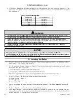
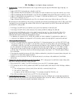
1. Safe, reliable operation of this boiler depends upon installation by a professional heating contractor in strict accordance
with this manual and the requirements of the authority having jurisdiction.
• In the absence of an authority having jurisdiction, installation must be in accordance with this manual
and the National Fuel Gas Code, ANSI Z223.1. In Canada, installation must be in accordance with the B149.1
Installation Code.
• Where required by the authority having jurisdiction, this installation must conform to the
Standard for Controls
and Safety Devices for Automatically Fired Boilers
(ANSI/ASME CSD-1).
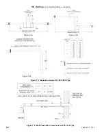
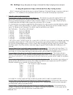
2. Read Section VII to verify that the maximum combustion air and exhaust pipe lengths will not be exceeded in the
planned installation. Also verify that the vent terminal can be located in accordance with Section VII.
3. Make sure that the boiler is correctly sized:
• For heating systems employing convection radiation (baseboard or radiators), use an industry accepted sizing
method such as the
I=B=R
Guide RHH published by the Air-Conditioning, Heating and Refrigeration Institute
(AHRI).
• For new radiant heating systems, refer to the radiant tubing manufacturer’s boiler sizing guidelines.
• For system which includes an indirect water heater, make sure the boiler has the output called for by the indirect
water heater manufacturer’s instructions.
III. Before Installing
II. Specifications
(continued)
Summary of Contents for K2WT-080B
Page 83: ...83 107672 01 7 17 PAGE LEFT INTENTIONALLY BLANK...
Page 89: ...89 107672 01 7 17 X Wiring continued Figure 10 5 Internal Ladder Diagram...
Page 90: ...90 107672 01 7 17 X Wiring continued...
Page 91: ...91 107672 01 7 17 Figure 10 6 Internal Wiring Connections Diagram X Wiring continued...
Page 102: ...102 107672 01 7 17 Lighting and Operating Instructions XI Start Up and Checkout continued...
Page 147: ...147 107672 01 7 17 XV Service Parts continued...
Page 151: ...151 107672 01 7 17 XV Service Parts continued...
Page 153: ...153 107672 01 7 17 XV Service Parts continued 85 86 91 95...
Page 162: ...162 107672 01 7 17...
Page 163: ...163 107672 01 7 17...
Page 164: ...164 107672 01 7 17...
Page 165: ...165 107672 01 7 17...
Page 166: ...166 107672 01 7 17...
Page 167: ...167 107672 01 7 17...


