58
Figure
Number
Page
Number
Description
Section VII - Oil Piping
Figure 17
27
Single-Pipe Installation
Figure 18
28
Two-Pipe Installation
Section VIII - System Start-Up
Figure 19
31
Electrode Tip Gap & Spacing
Figure 20
31
Riello Electrode Setting
Figure 21
31
Riello Turbulator Setting
Figure 22
32
Checking / Adjusting Fuel Pump Pressure
Figure 23
32
Riello Pump Connections and Port Identification
Figure 24
32
Cad Cell Location
Figure 25
33
GeniSys 7505 Oil Primary Terminals, LED's and Reset Button
Section IX - Operating
Figure 26
35
Intelligent Oil Boiler Control - Horizontal Mount Shown
Figure 27
35
Boiler Control Key Function & Orientation
Section XI - Boiler Cleaning
Figure 28
42
Cleaning of LEDV Boiler Firetubes / Combustion Chamber
Section XIII - Repair Parts
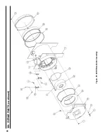
Figure 29
48
LEDV Bare Boiler Assembly
Figure 30
50
LEDV Boiler Jacket & Insulation
Figure 31
51
LEDV Boiler Trim & Controls
Figure 32
52
Beckett AFII Oil Burner Repair Parts
Figure 33
55
Vent Kit Repair Parts
Appendix A - Low Water Cut Off (LWCO) on Hot Water Boilers
N/A
56
LWCO Location
N/A
56
Wiring of Typical LWCO
APPENDIX B: FIGURES (continued)
Summary of Contents for LE DV Series
Page 5: ...5 I General Information Figure 1A LEDV Packaged Water Boiler with Beckett AFII Burner ...
Page 6: ...6 I General Information continued Figure 1B LEDV Packaged Water Boiler with Riello BF Burner ...
Page 19: ...19 v venting continued Figure 11 Vent Installation Figure 12 Vent Connector Un Assembled ...
Page 20: ...20 v venting continued Figure 13 Vent Connector Assembled Figure 14 Air Intake Installation ...
Page 48: ...48 xiii Repair Parts continued Figure 29 LEDV Bare Boiler Assembly ...
Page 50: ...50 xiii Repair Parts continued Figure 30 LEDV Boiler Jacket Insulation ...
Page 55: ...55 xiii Repair Parts continued Figure 33 Vent Kit Repair Parts ...
Page 60: ...60 U S Boiler Company Inc P O Box 3020 Lancaster PA 17604 1 888 432 8887 www usboiler net ...

