background image

 A.


EVALUATE  THE  ExISTING  STEAM  SYSTEM.


The single most important factor in determining the 

expected life cycle of a steam boiler, is the amount of 

fresh water added to the boiler during operation.  Fresh 

water brings minerals and oxygen into the boiler.  These 

contaminants greatly accelerate corrosion of the cast 

iron boiler sections.

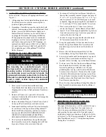
1.  Assure that all system radiators, piping and vents are 

absolutely leak tight.
a.  When a steam boiler is installed in an existing 

system, ALL air vents should be replaced at the 

same time.  This assures that the new boiler will 

not be compromised by existing system leaks.

b.  If the system contains hidden supply or return 

piping (hidden behind walls, buried in concrete, 

etc.) pressure test this piping to assure there are 

no leaks.

SECTION  III:  STEAM  BOILER  PIPING  & TRIM

2.  Repair any leaks in the system.
3.  Install accurate water meter on the fresh water 

supply to the boiler.

B.  CONNECT  SYSTEM  SUPPLY  AND  RETURN 

PIPING  TO  BOILER.

  See Figure 12 for piping 

details.  Also consult I=B=R Installation and Piping 

Guides.

CAUTION

Maintain  minimum  ½  inch  clearance  from  hot 

water piping to combustible materials.

WARNING

Failure to properly pipe boiler may result in improper operation and damage to boiler or structure.
Do not increase steam boiler input above the ratings.

NOTICE

Do not use softened water in steam boilers.  Accelerated boiler corrosion will result.  Tie in fresh water 

supply to the boiler upstream of a water softener.
Oxygen contamination of boiler water will cause corrosion of iron and steel boiler components, and can 

lead to boiler failure.  U.S. Boiler Company's Standard Warranty does not cover problems caused by 

oxygen contamination of boiler water or scale (lime) build-up caused by frequent addition of water.

Before using copper for steam piping, consider the following characteristics of copper piping:

    1)  high coefficient of thermal expansion can induce mechanical stresses and cause expansion/            

         contraction noises if not accounted for in the piping system design and installation,
    )  high heat transfer rate (heat loss) of uninsulated copper piping must be included in the normal 

         piping and pickup factors used to size the boiler,

    3)  soldering or brazing pastes and fluxes that end up in the system can cause poor heat transfer, 

         surging, an unsteady water line and wet steam if not thoroughly removed during the boil out 

         procedure and,
   )  galvanic corrosion of the adjoining metal may occur due to dissimilar metals in certain water

        chemistries if dielectric unions are not used.

Summary of Contents for MegaSteam MST

Page 1: ...L I O B L I O S S A P 3 g n i k e e s n e h W r e i l p p u s l i o r o r o t c a r t n o c g n i t a e h r u o y l l a c r e l i o b o t s r i a p e r r o e c i v r e s r o F g n i t a R n o n w o h...

Page 2: ...ace rust on cast iron sections may be attributed to the manufacturing process as well as condensation during storage Surface rust is normal and does not affect the performance or longevity of a boiler...

Page 3: ...and Steam Boiler Trim Piping Sections of this manual for details It is the responsibility of the installing contractor to see that all controls are correctly installed and are operating properly when...

Page 4: ...ols which may cause the boiler to shut down and not re start without service If damage due to frozen pipes is a possibility the heating system should not be left unattended in cold weather or appropri...

Page 5: ...Figure 1 MST288 Thru MST629 Steam Boiler with and without Tankless Heater Beckett Burner Shown...

Page 6: ...6 15 3 14 9 20 29 607 MST513 28 5 8 30 6 19 7 19 3 27 29 744 MST629 34 5 8 36 7 24 1 23 8 34 29 881 NOTE 1 Maximum Working Pressure Steam 15 PSI Boiler Model No Burner Capacity I B R NET Ratings Minim...

Page 7: ...ay cleaning MST513 36 for flueway cleaning MST629 b Clearance from Jacket Left Side Panel 19 for burner swing door if opened fully with burner mounted otherwise 1 with burner removed 12 access clearan...

Page 8: ...ett burner Metal cover applications P N 611280031 Plastic cover applications P N 102119 01 Refer to Fresh Air Accessory Kit Instructions for installation and air intake piping details or b Outdoor air...

Page 9: ...Heater Part 100567 05 100045 02 100021 01 2 ___ Control Carton ____ CG450 LWCO W Tankless Heater Part 100608 01 ____ PS801 LWCO W Tankless Heater Part 100622 01 ____ 67 LWCO W Tankless Heater Part 100...

Page 10: ...ng skid with four lag screws Remove the screws and discard 6 For manual Cast Iron Section Burner Swing Door Smoke Box Assembly removal prepare one piece of 4 x 4 x 16 lg or two pieces of 2 x 4 x 16 lg...

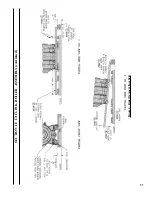
Page 11: ...11 Figure 4 Boiler Removal from Skid SECTION II UNIT PAK BOILER ASSEMBLY continued...

Page 12: ...ent points See also Figure 7 Purpose of Tappings Bosses 2 Open Jacket Carton and locate jacket front panel has factory attached 1 fiberglass insulation See also Repair Parts Section Jacket Assembly il...

Page 13: ...de 2nd and 3rd pass flueways should make an impression in door insulation to seal the chambers By design door insulation on model MST629 will have two by pass pockets cast into the insulation centered...

Page 14: ...temperatures Under certain conditions a lower gross stack temperature entering the chimney has the potential to be cooled below the dew point and create condensate on interior surfaces Flue gas conden...

Page 15: ...lternating tightening method from right side tap bolt to left side tap bolt to tighten door equally until sealed without applying excessive torque NEVER TIGHTEN LEFT SIDE TAP BOLT FIRST OR EITHER PIEC...

Page 16: ...rol LWCO Float LWCO E 2 11 Supply Front Rear Tappings F 14 Safety Valve G 1 11 Condensate Return H 1 11 Optional Front Return J 1 11 Surface Blowoff Plugged K 1 11 Indirect Water Heater Supply L 14 In...

Page 17: ...fold Insulation Wrapper position it over section assembly centered left to right and align two wrapper upper holes with 2 NPT pipe tappings in front and rear section top 4 Insure wrapper fits snugly a...

Page 18: ...harness from Control Carton 2 Locate and remove 1 4 NPT x 1 7 8 x 4 x 90 syphon enclosed in Part Carton 3 Review and locate pressure limit tapping on front section See Table 3 Purpose of Tappings Boss...

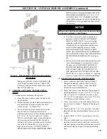
Page 19: ...19 Figure 9 Float Type LWCO and Pressure Limit Installation SECTION II UNIT PAK BOILER ASSEMBLY continued...

Page 20: ...rnal electrical enclosure top flange front left 7 8 hole then snap in harness BX connector into the hole and plug in Molex connector into dedicated LWCO receptacle inside the enclosure middle left off...

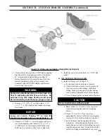
Page 21: ...1 1 2 x NPT black tee onto nipple end Black tee side outlet may be oriented to either left or right side 6 Install the drain valve into black tee NPT side outlet R Oil Burner Installation 1 Install oi...

Page 22: ...o Combustion Head Refer to Figure 11B v Check Insertion Depth Verify the distance between the tip of the end cone to face of the burner mounting flange is as specified in Table 8A Riello Burner Specif...

Page 23: ...er for connection to either a single or two line system Also supplied are two ADAPTORS 3 two female NPT to adapt oil lines to burner pipe connectors All pump port threads are British Parallel Thread d...

Page 24: ...pipe boiler may result in improper operation and damage to boiler or structure Do not increase steam boiler input above the ratings NOTICE Do not use softened water in steam boilers Accelerated boiler...

Page 25: ...25 Figure 12 Recommended Boiler Piping for Gravity Return Steam Boiler SECTION III STEAM Boiler PIPING TRIM continued...

Page 26: ...the user will not waste as much hot water while seeking a water temperature Higher temperature hot water required by dishwashers and automatic washers is possible by piping the hot water from the hea...

Page 27: ...3 Schematic Tankless Water Heater Piping Boiler Model Heater No Heater Rating GPM Pressure Drop thru Heater PSI MST288 222A 3 00 22 0 MST396 3 25 24 3 MST513 3 50 26 5 MST629 4 00 31 0 SECTION IV TANK...

Page 28: ...ater Heater Piping with MegaSteam Boiler B CONNECT Alliance SL INDIRECT WATER HEATER PIPING as shown in Figure 14 1 Refer to Alliance SL manual for additional information SECTION IV TANKLESS Indirect...

Page 29: ...shall be examined by a qualified person in accordance with the requirements of Chapter 11 of NFPA 211 Standard for Chimneys Fireplaces Vents and Solid Fuel Burning Appliances SECTION V VENTING Air int...

Page 30: ...30 Figure 15 Recommended Vent Pipe Arrangement and Chimney Requirements Figure 16 Proper and Improper Locations of Draft Regulator SECTION V VENTING Air intake piping continued...

Page 31: ...and temperature measurements may be different then those values in the table D Stack Temperature 1 The temperature of the flue gases has a significant effect on the amount of draft created in a verti...

Page 32: ...irectly to the burner from outdoors providing that the criteria for chimney vent connector and minimum stack temperature outlined in this section can be maintained ONLY AVAILABLE WITH BECKETT BURNER R...

Page 33: ...thermostat so there will be free movement of room air around this control Heat Anticipator in Thermostat should be set to match the requirements of the control to which it is connected See Figures 18...

Page 34: ...34 Figure 18 Wiring Diagram Steam Hydrolevel CG450 Probe LWCO SECTION VI ELECTRICAL continued...

Page 35: ...35 Figure 18A Wiring Diagram Riello 40 Series Burner Steam Hydrolevel CG450 Probe LWCO SECTION VI ELECTRICAL continued...

Page 36: ...36 Figure 19 Wiring Diagram Steam McDonnell Miller PS 801 Probe LWCO SECTION VI ELECTRICAL continued...

Page 37: ...37 Figure 19A Wiring Diagram Riello 40 Series Burner Steam McDonnell Miller PS 801 Probe LWCO SECTION VI ELECTRICAL continued...

Page 38: ...38 Figure 20 Wiring Diagram Steam McDonnell Miller 67 Float LWCO SECTION VI ELECTRICAL continued...

Page 39: ...39 Figure 20A Wiring Diagram Riello 40 Series Burner Steam McDonnell Miller 67 Float LWCO SECTION VI ELECTRICAL continued...

Page 40: ...be low water cut off will shut down the burner after a 10 15 second delay if the water level in the boiler drops below the probe level The probe low water cut off will reset and restart the burner wit...

Page 41: ...copper tubing Copper tubing shall have a 032 minimum wall thickness WARNING Under no circumstances can copper with sweat style connectors be used NOTICE Some jurisdictions require the use of a fusibl...

Page 42: ...al shutoff valve to be located on the return line of a two pipe system Accidental closure of the return line will rupture the oil pump seals Table 5 Two Stage Units 3450 RPM Two Pipe Systems Lift H Se...

Page 43: ...r more details A ALWAYS INSPECT INSTALLATION BEFORE STARTING BURNER 1 Verify that the venting water piping oil piping and electrical system are installed properly Refer to Installation Instructions co...

Page 44: ...lumn w c in the canopy Replace plug at completion See Tables 8 thru 8B at rear of this manual for details regarding the overfire pressure when baffles are both installed and removed 3 READJUST THE HEA...

Page 45: ...45 Figure 24 L1 and V1 Head Electrode Positioning and Gun Setting Beckett AFG Section VIII SYSTEM START UP continued...

Page 46: ...ost three times and does not successfully satisfy a call for heat the R7184 locks out iv Limited Reset Restricted Mode In order to limit the accumulation of unburned oil in the combustion area the con...

Page 47: ...me is established turn the power off to the control burner The burner should shut down safely When power is restored a normal ignition sequence should be started 3 WARNING Check Pressure Limit Control...

Page 48: ...Long sleeved loose fitting clothing 3 Gloves 4 Eye Protection Take steps to assure adequate ventilation Wash all exposed body areas gently with soap and water after contact Wash work clothes separatel...

Page 49: ...a moderate amount of good quality pipe dope to the pipe threads on the probe leaving the two end threads bare Do not use PTFE Teflon tape j Screw the probe into the boiler tapping k Mount the low wat...

Page 50: ...ain and at boiler as shown in Figure 12 and proceed as follows i Connect hoses from drain valves to floor drain Close gate valve in Hartford Loop and open drain valve in return main Fill boiler to nor...

Page 51: ...ppens the cast iron in that area gets extremely hot and eventually cracks The presence of free oxygen or chloride salts in the boiler corrodes the cast iron from the inside More make up water and high...

Page 52: ...n the bottom of the combustion chamber and smoke box B Clean the Combustion Chamber Use a wire or fiber bristle brush to clean the surfaces of the combustion chamber Vacuum all of the loose debris in...

Page 53: ...quate chimney The interior of the chimney flue must be inspected and cleaned before the start of the heating season and should be inspected periodically throughout the heating season for any obstructi...

Page 54: ...pump Water in the fuel in smaller amounts will cause excessive wear on the pump but more importantly water doesn t burn It chills the flame and causes smoke and unburned fuel to pass out of the combus...

Page 55: ...to provide lockout in the event of a stuck or welded motor relay NOTICE If flame is not established within 15 seconds of oil valve actuation known as Trial For Ignition TFI lockout will occur Lockout...

Page 56: ...am product distributor Should you require assistance in locating a Burnham product distributor in your area or have questions regarding the availability of Burnham brand products or repair parts pleas...

Page 57: ...61012 1 Lower Tie Rod 3 8 16 x 27 Lg 80861018 1 1G 3 8 Flat Washer USS Plain 80860600 4 4 4 4 1H 3 8 16 Heavy Hex Nut Plain 80860400 4 4 4 4 1J Spanner Bar w Threaded Inserts 1 1 4 x 1 1 2 x 20 3 8 Lg...

Page 58: ...58 Bare Boiler Assembly SECTION XII Repair Parts continued...

Page 59: ...2 2 1AA Smokebox 100021 01 1 1 1 1 1BB 5 16 Flat Washer USS Plated 80860611 4 4 4 4 1CC Cap Screw 5 16 18 x 3 4 Lg Plated 80861340 4 4 4 4 1DD 1 4 NPT Pipe Plug Square Head Brass 806603542 1 1 1 1 1EE...

Page 60: ...60 Jacket Assembly SECTION XII Repair Parts continued...

Page 61: ...1 100614 05 1 2K Jacket Left Side Panel 3 Section 100581 03 1 1 Jacket Left Side Panel 4 Section 100581 04 1 Jacket Left Side Panel 5 Section 100581 05 1 2L Jacket Right Side Panel 3 Section 100583 03...

Page 62: ...62 MST288 Thru MST629 Steam Boilers Trim and Controls SECTION XII Repair Parts continued...

Page 63: ...530 1 1 1 1 3M Gauge Glass Set 6 Conbraco 20 104 10 8056091 1 1 1 1 3N Low Water Cut off McDonnell Miller 67 80160597 1 1 1 1 3P Nipple 1 1 2 NPT x 5 Lg 808600060 1 1 1 1 3Q Tee 1 1 2 x 1 1 2 x 3 4 80...

Page 64: ...64 Beckett AFG Burner SECTION XII Repair Parts continued...

Page 65: ...w 4219 4219 4219 4219 Electrode Insulator Assembly 5780 5780 5780 5780 Support Spacer Assembly 5992 5992 5992 5992 Escutcheon Plate Adjusting Plate Assembly 5941 5941 5941 5941 Head 5913 5913 5913 591...

Page 66: ...tts 800 992 7637 Riello Canada Inc 2165 Meadowpine Blvd Mississauga Ontario L5N 6H6 Telephone 905 542 0303 Facsimile 905 542 1525 Toll Free 800 387 3898 SECTION XII Repair Parts continued CARLIN OIL B...

Page 67: ...ump is standard two stage fuel pump is optional Burner manufacturer has preset single stage fuel pump to settings shown in table above Two stage fuel pump is factory set at 140 PSI and must be readjus...

Page 68: ...1 65 EZ 66 1 35 x 45B Hago 5 5 60 150 Conical Wrap 2 5 8 11 5 2 nd 18 0 0 050 0 030 Notes 2 The increased stack temperature with the baffles removed is an approximation based on a constant supply temp...

Page 69: ...e Replacement Figure 11C 22 Electrode Setting Figure 11D 23 Turbulator Setting Figure 11E 23 Pump Connections and Port Identification Section III Steam Boiler Piping Trim Figure 12 25 Recommended Boil...

Page 70: ...Fuel Pump Pressure Figure 24 45 L1 and V1 Head Electrode Positioning and Gun Setting Beckett AFG Figure 25 46 R7184 Terminals LED and Reset Button Figure 26 47 Cad Cell Location Section X Boiler Clea...

Page 71: ...Indirect Water Heater Piping Table 4 27 Tankless Heater Data Section VII Oil Piping Table 5 42 Two Stage Units 3450 RPM Two Pipe Systems Table 6 42 Single Stage Units 3450 RPM Two Pipe Systems Section...

Page 72: ...72 U S Boiler Company Inc P O Box 3020 Lancaster PA 17604 717 397 4701 www usboiler burnham com...

Reviews: