background image

   103536-13 - 2/24

9700609

Installation, Operating and Service Instructions for

MegaSteam

TM

TO THE INSTALLER: 

Affix these instructions adjacent to boiler.

TO THE CONSUMER: 

Retain these instructions for future reference.

For service or repairs to boiler, call your heating contractor.  When seeking information on boiler, provide 

Boiler Model Number and Serial Number as shown on Rating Label.

Models:
• MST288
• MST396
• MST513
• MST629
• MST758
• MST892

• Natural Draft

• Oil-Fired, 3 Pass

• Steam Boiler

• B20 Ready

Manual Contents                                           Page
1.   Pre-installation 
  . . . . . . . . . . . . . . . . . . . . . . 5
2.  Unit-Pak Boiler Assembly 
. . . . . . . . . . . . . . 9
3.   Steam Boiler Piping & Trim 
  . . . . . . . . . . . 21
4.   Tankless & Indirect Water Heater Piping
 . 27
5.   Venting & 
Air Intake Piping   . . . . . . . . . . . 30
6.   Electrical 
  . . . . . . . . . . . . . . . . . . . . . . . . . . 34
7.    Oil Piping  
. . . . . . . . . . . . . . . . . . . . . . . . . . 39
8.   System Start-up
 . . . . . . . . . . . . . . . . . . . . . 41
9.   Maintenance & Service Instructions  
. . . . 46
10.  Boiler Cleaning
  . . . . . . . . . . . . . . . . . . . . . 49
11. Troubleshooting 
  . . . . . . . . . . . . . . . . . . . . 51
12.  Service Parts  
. . . . . . . . . . . . . . . . . . . . . . . 53
Appendix A: Steam Boiler Skimming . . . . . . . 60
Appendix B: After Market Low Water Cut-off 
(LWCO)  . . . . . . . . . . . . . . . . . . . . . . . . . . . . . . . 61

Summary of Contents for MegaSteam MST758

Page 1: ...mber as shown on Rating Label Models MST288 MST396 MST513 MST629 MST758 MST892 Natural Draft Oil Fired 3 Pass Steam Boiler B20 Ready Manual Contents Page 1 Pre installation 5 2 Unit Pak Boiler Assembl...

Page 2: ...t Edition of American Society of Mechanical Engineers ASME CSD 1 Controls and Safety Devices for Automatically Fired Boilers for assembly and Controls and Safety Devices for Automatically Fired Boiler...

Page 3: ...rear section See Unit Pak Boiler Assembly and Steam Boiler Trim Piping Sections of this manual for details It is the responsibility of the installing contractor to see that all controls are correctly...

Page 4: ...ust be installed so there are provisions for adequate combustion and ventilation air This boiler is supplied with controls which may cause the boiler to shut down and not re start without service If d...

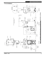
Page 5: ...5 103536 13 2 24 MegaSteam Installation Service Manual Figure 1 1 MST288 Thru MST629 Steam Boiler with Tankless Heater Beckett Burner Shown 1 Pre Installation...

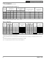
Page 6: ...r Capacity DOE Heating Capacity MBH 2 Gross Output MBH 2 AHRI NET Ratings AFUE Thermal Efficiency GPH MBH 1 Steam MBH 3 Steam Sq Ft MST288 0 75 105 92 69 288 86 0 MST396 1 05 147 127 95 396 86 0 MST51...

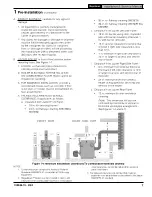
Page 7: ...be installed in rooms with clearances from combustible material as listed above Listed clearances cannot be reduced for alcove or closet installations 3 For reduced clearances to combustible material...

Page 8: ...be provided with an optional U S Boiler Company Fresh Air Accessory Kit ONLY AVAILABLE WITH BECKETT BURNER P N 102119 01 Refer to Fresh Air Accessory Kit Instructions for installation and air intake...

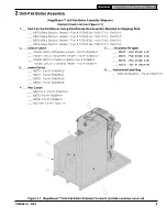
Page 9: ...__ MST3 Rear Section Heater Part 107242 03 102417 01 100021 01 ____ MST4 Rear Section Heater Part 107242 04 102417 01 100021 01 ____ MST5 Rear Section Heater Part 107242 05 102417 02 100021 01 ____ MS...

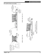
Page 10: ...moval prepare one piece of 4 in x 4 in x 16 in lg or two pieces of 2 in x 4 in x 16 in lg and two pieces of 1 in Sch 40 black pipe to be used as handles Suggested pipe length for each handle is 72 in...

Page 11: ...11 103536 13 2 24 MegaSteam Installation Service Manual Figure 2 2 Boiler Removal from Skid 2 Unit Pak Boiler Assembly continued...

Page 12: ...or mounting bracket attachment points 2 Unit Pak Boiler Assembly continued See also Figure 2 8 Purpose of Tappings Bosses 2 Open Jacket Carton and locate jacket front panel has factory attached 1 in f...

Page 13: ...n the left and right side 2nd and 3rd pass flueways should make an impression in door insulation to seal the chambers By design door insulation on model MST629 MST758 will have two by pass pockets cas...

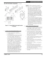
Page 14: ...ide baffle in flueway until position tab touches fins on right side of 2nd pass flueway To install flueway baffle in 2nd pass flueway on right side of boiler hold baffle with word Right readable at th...

Page 15: ...qually until sealed without applying excessive torque NEVER TIGHTEN LEFT SIDE TAP BOLT FIRST OR EITHER PIECE OF HARDWARE 100 WITHOUT USING THE ALTERNATING METHOD DESCRIBED ABOVE See Figure 2 4 e Failu...

Page 16: ...ings F in 14 Safety Valve G 1 in 11 Condensate Return H 1 in 11 Optional Front Return J 1 in 11 Surface Blowoff Plugged K 1 in 11 Indirect Water Heater Supply L in 14 Indirect Water Heater Limit M 4 p...

Page 17: ...RAPPER AND BURNER POWER OUTLET RECEPTACLE WITH HARNESS INSTALLATION 1 Insulation Wrapper is vacuum packed sealed in plastic bag at the factory 2 Carefully cut the plastic bag and remove Insulation Wra...

Page 18: ...ce 7 Install 8 x in sheet metal screw thru enclosure base lower hole located to the right of transformer relay into right side panel to secure the enclosure 8 Plug in burner harness Molex connector in...

Page 19: ...with tankless heater install the L4006A aquastat controller well found in Part Carton into in NPT tapping in tankless heater plate 2 Remove the L4006A aquastat controller with factory attached harness...

Page 20: ...or mounting burner d Thread 1 5 16 18 x 3 4 lg cap screw approximately three 3 full turns into tapping located at 12 00 o clock on burner swing door e Insert oil burner into the opening of burner swin...

Page 21: ...nd MST513 2 Assemble Gravity Return Piping Kit for MST629 MST758 and MST892 as illustrated in Figure 3 5 for Recommended configuration or Figure 3 9 for Dropped Header configuration See Table 3 4 for...

Page 22: ...22 103536 13 2 24 MegaSteam Installation Service Manual Figure 3 1 Recommended Boiler Piping for Gravity Return Steam Boiler 3 Steam Boiler Piping Trim continued...

Page 23: ...4 in Nipple 101436 01 1 13 1 1 2 in Wye 101437 01 1 14 1 1 2 in 1 1 4 in Bush 806600539 2 15 1 1 4 in x 22 3 16 in Nipple 106711 01 1 16 1 1 4 in x 3 4 in x 1 1 4 in Tee 806601002 2 17 1 1 4 in x 9 7...

Page 24: ...ee 806601108 1 12 2 in x 10 in Nipple 806600037 1 13 2 in x 13 3 8 in Nipple 101441 01 1 14 2 in Wye 806601124 1 15 2 in 1 1 2 in Bush 806600517 1 16 1 1 2 in x 20 5 8 in Nipple 101442 01 1 17 1 1 2 i...

Page 25: ...2 in x 4 3 4 in Nipple 101436 01 1 14 1 1 2 in Wye 101437 01 1 15 1 1 2 in 1 1 4 in Bush 806600539 2 16 1 1 4 in x 22 3 16 in Nipple 106711 01 1 17 1 1 4 in x 3 4 in x 1 1 4 in Tee 806601002 2 18 1 1...

Page 26: ...n Tee 806601079 1 12 3 in Tee 806601108 1 13 2 in x 7 3 8 in Nipple 101907 01 1 14 2 in Wye 806601124 1 15 2 in 1 1 2 in Bush 806600517 1 16 1 1 2 in x 20 5 8 in Nipple 101442 01 1 17 1 1 2 in x 1 1 2...

Page 27: ...te as much hot water while seeking a water temperature Higher temperature hot water required by dishwashers and automatic washers is possible by piping the hot water from the heater prior to entering...

Page 28: ...s Water Heater Piping Boiler Model Heater No Intermittent Draw GPM Pressure Drop thru Heater PSI MST288 222B 3 00 19 5 MST396 3 25 28 7 MST513 3 50 32 5 MST629 4 00 36 2 MST758 4 25 43 3 MST892 4 50 4...

Page 29: ...anual Figure 4 3 Alliance SL Water Heater Piping with MegaSteam Boiler B CONNECT ALLIANCE SL INDIRECT WATER HEATER PIPING as shown in Figure 4 3 1 Refer to Alliance SL manual for additional informatio...

Page 30: ...Prior to the installation of any new or replacement fuel burning equipment the chimney shall be inspected by a qualified installer The chimney shall be inspected for integrity as well as for proper dr...

Page 31: ...3 2 24 MegaSteam Installation Service Manual Figure 5 1 Recommended Vent Pipe Arrangement and Chimney Requirements Figure 5 2 Proper and Improper Locations of Draft Regulator 5Venting Air Intake Pipin...

Page 32: ...e outlet of boiler a Type L or a factory built chimney material that complies with the Type HT requirements of ANSI UL 103 Install in accordance with listing and manufacturer s instructions b Steel pi...

Page 33: ...cy of the boiler is based on the insertion of flue baffles supplied with your product Under no circumstances are other baffles to be used on this product Refer to Section 2 Item E for baffle installat...

Page 34: ...ture away from thermostat so there will be free movement of room air around this control Heat Anticipator in Thermostat should be set to match the requirements of the control to which it is connected...

Page 35: ...24 MegaSteam Installation Service Manual Figure 6 1 Wiring Diagram Hydrolevel CG450 Probe LWCO SEE FIGURE 6 3 FOR SCHEMATIC WIRING DIAGRAM OF APPROPRIATE BURNER AND OIL PRIMARY CONTROL OPTION 6 Electr...

Page 36: ...egaSteam Installation Service Manual Figure 6 2 Wiring Diagram McDonnell Miller PSE 801 Probe LWCO SEE FIGURE 6 3 FOR SCHEMATIC WIRING DIAGRAM OF APPROPRIATE BURNER AND OIL PRIMARY CONTROL OPTION 6 El...

Page 37: ...37 103536 13 2 24 MegaSteam Installation Service Manual Figure 6 3 Schematic Wiring Diagram Beckett 6 Electrical continued...

Page 38: ...water temperature at the selected setting for proper operation of the domestic water heater if equipped with optional tankless heater BOILER SEQUENCE OF OPERATION WITH PROBE LWCO See Figure 6 2 When...

Page 39: ...uire the use of a fusible electrical interlock with the burner circuit Check your local Codes for special requirements B SINGLE PIPE OIL LINES 1 Standard burners are provided with single stage 3450 rp...

Page 40: ...tem Accidental closure of the return line will rupture the oil pump seals Lift H Figure 7 4 Maximum Length of Tubing H R 3 8 in OD Tubing 3 GPH 1 2 in OD Tubing 3 GPH 0 ft 93 ft 100 ft 2 ft 85 ft 100...

Page 41: ...e details A ALWAYS INSPECT INSTALLATION BEFORE STARTING BURNER 1 Verify that the venting water piping oil piping and electrical system are installed properly Refer to Installation Instructions contain...

Page 42: ...rate the burner automatically If for unknown reasons the burner ceases to fire and the reset button on the primary control has tripped the burner has experienced ignition failure WARNING Do not attemp...

Page 43: ...ation 2 Safe Start Check a Place a jumper across the cad cell terminals b Initiate a call for heat c Burner must not start Verify that the SYS light is green FLM light is yellow and that the control r...

Page 44: ...events excessive accumulation of oil in the appliance firing chamber i Lockout The control has shut down for one of the following safety reasons i The trial for ignition lockout time expired without f...

Page 45: ...soft 1 Second Tap Reset Control Lockout hard 15 Seconds Reset Control Valve On Delay For Ignition or Carryover 1 Second Tap Go to pump after pump priming is enabled per the next step Powered On 15 Sec...

Page 46: ...g that is sufficiently tight around potential entry points for RCF dust 3 Gloves 4 Eye protection such as goggles safety glasses with side shields or full facepiece Take steps to assure adequate venti...

Page 47: ...Clean the pipe threads of the probe to remove old hardened pipe dope and other foreign matter i Apply a moderate amount of good quality pipe dope to the pipe threads on the probe leaving the two end...

Page 48: ...the appropriate amount of a recommended boilout compound Remove safety valve from boiler and pour this solution into boiler then reinstall safety valve iii Turn on oil burner and keep operating while...

Page 49: ...boiler sooner Our warranty does not cover oxygen corrosion and sediment related damage Clearly it is in everyone s best interest to prevent this type of failure You can do your part by ensuring that...

Page 50: ...s in the bottom of the combustion chamber and smoke box B CLEAN THE COMBUSTION CHAMBER Use a wire or fiber bristle brush to clean the surfaces of the combustion chamber Vacuum all of the loose debris...

Page 51: ...could result if the boiler is connected to a dirty or inadequate chimney The interior of the chimney flue must be inspected and cleaned before the start of the heating season and should be inspected...

Page 52: ...the smaller the slots become in the nozzle and the more prone to plugging it becomes with the same amount of dirt 7 WATER Water in the fuel in large amounts will stall the fuel pump Water in the fuel...

Page 53: ...cks out after Trial For Ignition TFI a No oil to burner b Shorted electrodes c Nozzle clogged d Airflow too high e Ignitor module defective f CAD cell defective g Oil valve stuck open or closed Note T...

Page 54: ...obtained through your local U S Boiler Company Wholesale distributor Should you require assistance in locating a U S Boiler Company Distributor in your area or have questions regarding the availabilit...

Page 55: ...1 1 1C Burner Swing Door Assembly Includes Hinge and Hardware 109556 01 1 1 1 1 109557 01 1 1 1D Cleanout Cover Assembly 109563 01 2 2 2 2 2 2 1E Flue Collar Includes Hardware 109568 01 1 1 1 109569...

Page 56: ...56 103536 13 2 24 MegaSteam Installation Service Manual 12 Service Parts continued MegaSteam Water Boilers Trim...

Page 57: ...58 01 1 1 1 112560 01 1 112561 01 1 2F Low Water Cut off Includes Harness and Probe Hydrolevel CG450 109708 01 1 1 1 1 1 1 McDonnel Miller PSE801 109714 01 1 1 1 1 1 1 2G Pressure Limit Includes Harne...

Page 58: ...ber MST288 MST396 MST513 MST629 MST758 MST892 Not Shown Beckett Natural Draft 112210 01 1 112204 01 1 112205 01 1 112206 01 1 112555 01 1 112556 01 1 Primary Becket 7565 Obtain Locally 1 1 1 1 1 1 Bur...

Page 59: ...Pump Pressure psi MST288 1 0 75 AFG L1 6 1 0 60 x 60A Delavan 150 MST396 1 05 AFG L1 9 0 0 75 x 60B Delavan 180 MST513 1 35 AFG V1 2 7 1 1 00 x 60B Delavan 180 MST629 1 65 AFG V1 3 10 3 1 25 x 60B Hag...

Page 60: ...se valve You will not close this after the skimming process starts This pipe nipple must be horizontal and must come straight out It can not elbow up We are trying to skim the water surface therefore...

Page 61: ...Cut off LWCO WARNING DO NOT ATTEMPT to cut factory wires to install an aftermarket Low Water Cut Off LWCO Only use connections specifically identified for Low Water Cut Off In all cases follow the Lo...

Page 62: ...62 103536 13 2 24 MegaSteam Installation Service Manual U S Boiler Company LLC P O Box 3020 Lancaster PA 17604 1 888 432 8887 www usboiler net...

Reviews: