FORM NO. 56041894 - 5
SET-UP:
Fill the holding tank with clear water and the detergent of your choice. Mix well. Although this machine is designed to supply instant hot water,
the addition of warm or hot water to the holding tank would be a plus factor.
1. Plug in cord #1. This cord runs the pump and vacuums.
2. Turn on the pump and spray through the cleaning tool for a few seconds to fill the lines with solution.
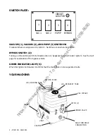
3. Plug in cord #2 (identified by a red “H”). IF THE GREEN LIGHT ILLUMINATES, THE HEAT EXCHANGER WILL TURN ON
AUTOMATICALLY (SEE NOTE BELOW). Wait 2 minutes for the heat exchanger to reach operating temperature. You may now begin
cleaning. It will take about 10 seconds for the initial heat to reach the wand.
NOTE: If the green circuit indicator light does not illuminate when cord #2 is plugged in, then both cores are on the same circuit. Try other
outlets until the light comes on. See bypass switch section (below) if you are unable to get a green light.
ELECTRIC CIRCUIT LOCATOR:
This unique, patented “smart system”, operated by a solid state circuit, will inform the operator when the two cords are plugged into separate
lines by illuminating the green indicator light. This helps prevent tripping circuit breakers.
BYPASS SWITCH:
The bypass switch completely bypasses the circuit locator. Use this feature when you cannot get the green light to come on and you believe that
the two cords are on separate circuits.
CAUTION: If the bypass switch is on and the two cords are plugged into the same circuit, the breaker may blow.
BALL FLOAT VAC SHUTOFF:
When the recovery tank is full, the float system will shut off the incoming air flow and prevent water from entering the vacuum motors. The float
may not work properly if the float filter is clogged or if there is foam in the tank.
CAUTION: To avoid vac motor damage, always make sure the float filter is clean and the ball travels freely before turning on the
machine, and use a defoamer whenever foam is present.
TROUBLE SHOOTING:
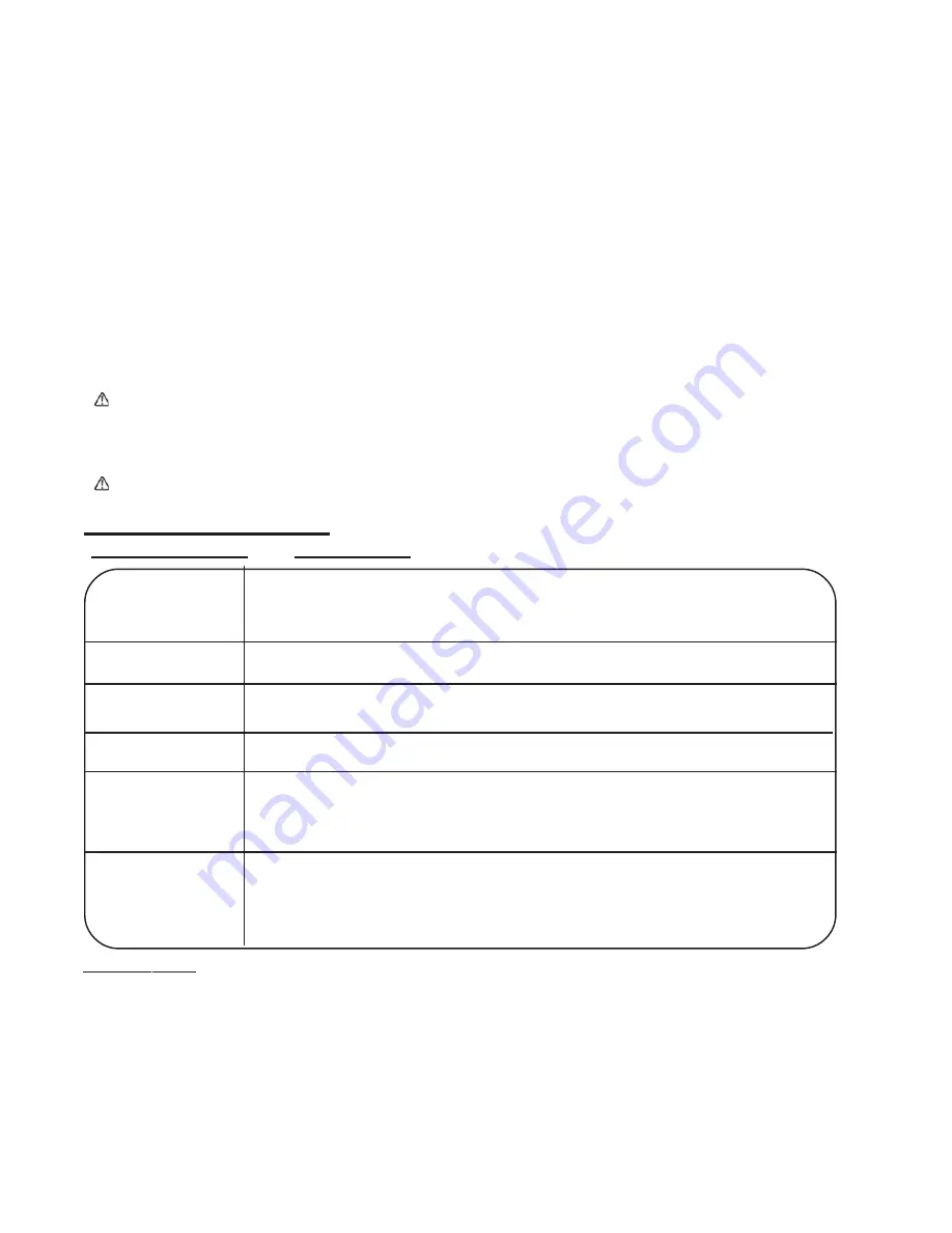
IF THIS OCCURS
CHECK THIS
NO SPRAY
PUMP WON’T RUN
Solution tank is empty.
Clogged spray tip.
Pump not running.
Valve on wand not operating
No power to pump. Test the switch. Test the pump motor. Replace if necessary.
Debris plugging cleaning tool or vacuum hose.
Drain gate is not completely closed, or seals are damaged. Vacuum lid is not closed or gasket is damaged.
No power to motor. Test the switch. Test the vacuum motor.
Spraying too long. Try spraying for 12-15 seconds per cycle.
Heat exchanger needs to be flushed.
Wrong tool being used.
Too much water passing through, longer hose or larger diameter hose, than standard
Heat is not turned on. Either the green light must be on or the bypass switch must be turned on.
No power in the wall outlet - check to see if the breaker has tripped.
No power to the bypass switch - check wiring for ‘opens’.
No power out of bypass switch, follow troubleshooting steps to isolate the problem or call your distributor for
additional help
LOW SUCTION
NO SUCTION
LOW HEAT
NO HEAT
SPECIFICATIONS:
Rotomolded Body:
Vacuum:
VAC Shutoff:
Pump:
Waterlift:
Heat:
Heater:
Weight:
Dimensions:
Lifetime Warranty
Two, 2-stage 5.7”
Ball float
Demand pump, 100 psi
150”
212º F
2000 Watts
75 lbs.
25.5H x 18W x 28.75L (inches)
revised 10/10
https://harrissupplyind.com - To Order Parts Call 608-268-8080


