background image

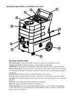
MACHINE DESCRIPTIONS

Operator Handle (1)

 - Operator holds this to move the machine from one location to another.

Solution Tank Lid (2)

 - Fill Solution Tank here with warm water and chemicals.

Switch Plate (3)

 - This is where the switches are located that operate the pump, vacuum and heater.

Recovery Tank Lid (4) 

- The Recovery Tank can be flushed out by running clean water into this opening

with the Drain Gate 

(7)

 open.  The vacuum float Shut-OFF can also be accessed through this opening for

maintenance.

Vacuum Inlet (5)

 - This is where the vacuum hose attaches to the machine.

Latch (6) 

-


Open the latches to access the base compartment, which contains the motors and heater.

Drain Gate (7) 

-


Open this gate to drain the recovered solution out of the machine.  Be sure to keep this

gate clean.

Castor (8) 

-


The castor swivels for easy maneuvering in tight spots.

Wheel (9) 

-


Large, non-marking wheels for ease of transport.

Power Cords (10) 

-


Two, 25 foot cords, rated 12 gauge, 3 wire.  Do not use if either cord is damaged.

The cord with the red “H” at the retainer is the cord that operates the heat.  The other cord powers the

vacuum, pump, and cooling fan.

BECOME FAMILAR WITH YOUR NEW EXTRACTOR

1

2

3

4

5

6

7

10

9

8

Summary of Contents for Cobra-H3

Page 1: ...ularly monthly or more often to prevent a build up of minerals or chemicals in the pump and heat systems Follow the flush with a clear water rinse to remove any particles and to rinse the acid from th...

Page 2: ...risk of fire electric shock or injury Do not leave the maching unattended when it is plugged in Unplug the unit from the outlet when not in use and before servicing To avoid electric shock do not exp...

Page 3: ...d has a grounding plug that looks like the plug illustrated in Figure 1 below A temporary adapter illustrated in Figures 2 and 3 may be used to connect this plug to a 2 pole receptacle as shown in Fig...

Page 4: ...nance Vacuum Inlet 5 This is where the vacuum hose attaches to the machine Latch 6 Open the latches to access the base compartment which contains the motors and heater Drain Gate 7 Open this gate to d...

Page 5: ...es to reach operating temperature 6 Turn the pump on Turn the vacuum on NOTE the pump has a built in pressure switch the pump runs only when you are spraying 7 Begin cleaning using the correct hoses a...

Page 6: ...seals are damaged Internal vacuum hose is cracked Recovery tank lid is not closed is cracked or gasket is damaged Recovery tank is warped or cracked Debris impeding air movement on vac motor impellor...

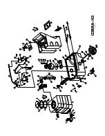
Page 7: ...25 21 22 40 41 42 43 44 45 46 47 53 48 55 49 58 50 51 52 62 69 14 16 66 67 68 COBRA H302 07 2006 19 56 24 11 12 13 14 33 28 32 35 63 38 37 30 65 61 60 59 58 69 57 55 54 53 36 31 34 22 25 26 29 27 31...

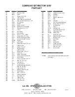
Page 8: ...100 psi 35 FP Heat Exchanger complete 36 5 Bolt 1 4 20 X 3 4 37 8 Lock nut 1 4 20 38 455 Bracket heater mount 39 76 Hose Clamp 40 270 Bolt 1 4 20 X 5 41 137 Washer split lock 42 136 Nut finish 1 4 43...

Reviews: