background image

8

SOLUS

®

 500R - 56041970

6/07

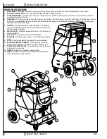
INSTRUCTIONS FOR USE

A - ENGLISH

SET-UP AND OPERATION

 CAUTION!

Use care when handling hazardous chemicals.
Never leave the machine running when you are not actively using it.
To avoid vacuum motor damage, always make sure the 

fl

 oat 

fi

 lter is clean and that it can travel freely before you operate the machine.  Always 

use a defoamer any time foam is present.

 DANGER!

Do NOT use solvents, or any chemicals that may be 

fl

 ammable, explosive or combustible.

CLEANING SOLUTIONS:

Select a proper pre-spray for the surface to be cleaned, and apply the pre-spray.  Use a neutral pH rinse or detergent (6 to 10 pH) in the Unit to 
prevent premature wear of the pumps, seals, and other components. Damage caused by the use of improper or strong chemicals is not covered 
by warranty.  Powdered chemicals are not recommended.

1.

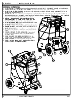
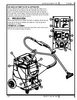
  Fill the holding tank 

(2) 

with clear water and pre-spray with the detergent of your choice (we recommend a CRI approved chemical).  Mix well.  

Although this machine is designed to supply instant hot water, the addition of warm water to the holding tank would increase heater ef

fi

 ciency.  


Never use water above 130º F/54º C in the solution tank.

2.

  Turn off all the switches.  Plug in cord #1. (This cord runs the pump and vacuum). 

NOTE: TURN THE HEAT RECIRCULATION SWITCH 

OFF BEFORE PRIMING THE PUMP.
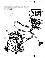
3.

  Attach the priming hose to the Solution Hose Quick Connect 

(10)

 and place the open end into the vacuum tank.

4.

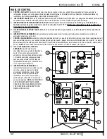
  Turn on the pump (turn pump pressure dial 

(F) 

all the way clockwise) and let it run until the pump is fully primed (approximately 30 seconds 

to 1 minute).  Once the pump is primed, turn off the pump and disconnect the priming hose.  Attach the cleaning hose 

(3 & 10)

 and tool.

IF YOU WANT HEATED SOLUTION:
5.

  Plug in the heater cord (identi

fi

 ed by “H” on the back of the machine). 

NOTE:

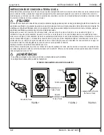
  If the Separate Circuit Locator Light 

(G) 

does not illuminate 

when the heater cord is plugged in, then both cords are on the same circuit.  Try other outlets until the light comes on.  See Bypass Switch 
section (below) if you are unable to get a green light.

6.

  Turn the Heat Control 

(A)

 clockwise to the desired temperature.

IF YOU WANT TO PRE-HEAT THE SOLUTION IN THE HOLDING TANK:
7.

  Turn on both the pump 

(F)

 and heat recirculation switches 

(C)

NOTE:

 this switch will recirculate heated water back to the holding tank, until 

it reaches 125 °F.  At that point, the recirculation will automatically stop.  If the temperature of the water in the tank drops below 125 °F, and if 
the recirculation switch is still turned ON, the system will begin to recirculate the water again until it gets back up to 125 °F.  You can choose 
to let the solution in your holding tank reach 125° or you can choose to begin cleaning sooner than that.

NOTE

: the time that it will take for your solution to reach 125 °F will vary with the temperature of the solution that you put into the tank, the 

ambient temperature, the amount of solution in your tank, etc.  

8.

  Turn on the pump 

(F) 

and spray through your tool a few times to 

fi

 ll the lines with solution.  Begin cleaning.

9.

 Re

fi

 ll and empty the tanks as necessary.

10.

 When 

fi

 nished with the job, vacuum all unused solution into the recovery tank, and dump the tank.  Clean the tanks and 

fi

 lters.  Clean the tool 

and hoses.  Store the machine in a heated location.

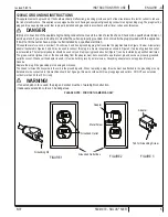
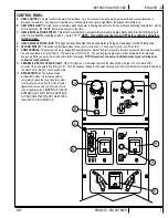
SEPARATE CIRCUIT LOCATOR

This unique, patented “smart system,” operated by a solid state circuit, will inform the operator when the two cords are plugged into separate lines 
by illuminating the green, indicator light.  This helps prevent tripping circuit breakers.

YOU MUST TURN THE HEAT RECIRCULATION SWITCH OFF BEFORE YOU CAN PRIME THE PUMP AND BEFORE YOU BEGIN 
CLEANING, OTHERWISE YOUR PUMP PRESSURE WILL BE VERY LOW.

BYPASS SWITCH

The Bypass Switch 

(H)

 completely bypasses the separate circuit locator system.  Use this feature when you cannot get the green Circuit Locator 

(G)

 to come on and you believe that the two cords are on separate circuits.

 CAUTION:

If the bypass switch is on when the two cords are plugged into the same circuit, the breaker in the wall panel may trip.

Summary of Contents for Solus 500R

Page 1: ...AL PRECAUCI N NO UTILICE LA M QUINA HASTA HABER LE DO TODAS LAS SECCIONES DE ESTE MANUAL DE INSTRUCCIONES ATTENTION N UTILISEZ PAS LA MACHINE AVANT D AVOIR LU TOUTES LES SECTIONS DU PR SENT MANUEL IMP...

Page 2: ...ng Instructions A 5 Know Your Machine A 6 A 7 Control Panel A 7 Set Up and Operation A 8 A 9 After Use After Using the Machine A 10 Maintenance Maintenance Schedule A 10 Power Cord Maintenance A 10 Tr...

Page 3: ...Use the space below to note the Model and Serial Number of your machine for future reference Model _________________________________________ Serial Number ___________________________________ UNPACKING...

Page 4: ...to a service center Do not pull by the cord use the cord as a handle close a door on the cord or pull the cord around sharp edges or corners Do not run the machine over the cord Keep the cord away fro...

Page 5: ...n Figures 2 and 3 may be used to connect this plug to a 2 pole receptacle as shown in Figure 2 if a properly grounded outlet is not available The temporary adapter should be used only until a properly...

Page 6: ...E be sure to close the cap tightly before using the machine again 1 2 3 4 5 8 9 10 12 13 6 7 11 11 5 HANDLES The handles are used to move the machine These handles allow you to tilt the machine back o...

Page 7: ...acuum motors are on The vacuum motors run off of cord 1 F PUMP CONTROL This dial controls motor speed and pump pressure Adjust the dial clockwise to increase pressure and counterclockwise to decrease...

Page 8: ...the same circuit Try other outlets until the light comes on See Bypass Switch section below if you are unable to get a green light 6 Turn the Heat Control A clockwise to the desired temperature IF YO...

Page 9: ...the vacuum motor shuts off the Vacuum Switch E must be turned off the recovery tank emptied and then the vacuum switch turned back on up position to get the vacuum motor started again CAUTION Always...

Page 10: ...SCHEDULE MAINTENANCE ITEM Daily Weekly Yearly Check Clean Tanks Hoses Check Clean Recovery Tank Shut Off Float Clean Extraction Wand Tool Inspect Clean Solution Filters Check Carbon Brushes IMPORTANT...

Page 11: ...praying for 12 15 seconds or about three strokes Heat exchanger needs to be flushed Wrong tool being used Too much water passing through Longer hose or larger diameter hose than standard NO HEAT Heat...

Page 12: ...de control B 7 Configuraci n y operaci n B 8 B 9 Despu s de la utilizaci n Despu s de la utilizaci n de la m quina B 10 Mantenimiento Programa de mantenimiento B 10 Mantenimiento del cable de aliment...

Page 13: ...uestos para la m quina Utilice el siguiente espacio para anotar el modelo y el n mero de serie de su m quina para futuras consultas Modelo ________________________________________ N mero de serie ____...

Page 14: ...cerrar una puerta y no tire de l contra bordes afilados ni esquinas No haga pasar la m quina por encima del cable Mantenga el cable alejado de superficies calientes Para desenchufar agarre el enchufe...

Page 15: ...usar un adaptador provisorio tal como se ve en las Figuras 2 y 3 en caso de disponerse de un recept culo sin toma a tierra como en la Figura 2 Dicho adaptador provisorio se usar solamente hasta que un...

Page 16: ...bien el tap n antes de volver a usar la m quina 5 MANIJAS Las manijas se usan para trasladar la m quina Estas manijas permiten inclinar la m quina sobre sus ruedas de 12 para maniobrarla f cilmente y...

Page 17: ...aspiraci n funcionan con el cable 1 F CONTROL DE LA BOMBA Este bot n controla la velocidad del motor y la presi n de la bomba G relo en el sentido de las agujas del reloj para aumentar la presi n y en...

Page 18: ...del calefactor entonces ambos cables est n en el mismo circuito Pruebe con otros tomas hasta que se encienda la luz Si no consigue que se encienda la luz verde consulte la secci n sobre el interruptor...

Page 19: ...motor de aspiraci n se debe apagar el interruptor de aspiraci n E vaciar el dep sito de recuperaci n y luego volver a encender el interruptor de aspiraci n posici n hacia arriba para que el motor de a...

Page 20: ...ubos Limpiar e inspeccionar el flotador de cierre del dep sito de recuperaci n Limpiar la varilla herramienta de extracci n Limpiar e inspeccionar los filtros de la soluci n Verificar los cepillos de...

Page 21: ...masiado prolongada Intente pulverizar durante 12 15 segundos o unos tres golpes Es necesario limpiar el intercambiador de calor Se est utilizando una herramienta equivocada Pasa demasiada agua Tubo m...

Page 22: ...pprenez conna tre votre machine C 6 C 7 Panneau de commande C 7 Installation et fonctionnement C 8 C 9 Apr s l utilisation Apr s l utilisation de la machine C 10 Entretien Programme d entretien C 10 E...

Page 23: ...espace disponible ci dessous pour consigner ces renseignements en vue d une utilisation ult rieure Mod le ________________________________________ Num ro de s rie _________________________________ D...

Page 24: ...il par le cordon lectrique N utilisez pas non plus le cordon comme une poign e et ne l enroulez pas autour d objets pointus ou tranchants vitez galement de refermer une porte sur le cordon vitez de fa...

Page 25: ...Figure 2 si une prise correctement mise la terre n est pas disponible L adaptateur temporaire doit tre utilis jusqu ce qu une prise correctement mise la terre Figure 1 soit install e par un lectricien...

Page 26: ...1 11 rincer la salet et les d bris pr sents dans le r servoir NOTE n oubliez pas de fermer correctement le bouchon avant de r utiliser la machine 5 POIGN ES Les poign es servent d placer la machine Ce...

Page 27: ...nnent partir du cordon 1 F COMMANDE DE LA POMPE ce bouton contr le la vitesse du moteur et la pression de la pompe Tournez le bouton en sens horaire pour augmenter la pression et en sens horaire inver...

Page 28: ...hangeur de chaleur est branch alors les deux cordons sont reli s au m me circuit Essayez d autres prises jusqu ce que le t moin s allume Consultez la section sur l Interrupteur de D rivation ci dessou...

Page 29: ...pteur d aspiration E doit tre plac en position d arr t le r servoir de r cup ration doit tre vid et l interrupteur d aspiration doit ensuite tre replac en position de marche position haute pour red ma...

Page 30: ...age des r servoirs et tuyaux V rification nettoyage du syst me de fermeture flotteur du r servoir de r cup ration Nettoyage de l accessoire lance d extraction Inspection et nettoyage des filtres de so...

Page 31: ...HAUFFAGE FAIBLE Pulv risation trop longue Tentez de vaporiser pendant 12 15 secondes ou environ trois appuis L changeur de chaleur doit tre nettoy Mauvais accessoire utilis Circulation d une quantit d...

Page 32: ......

Page 33: ...Description K1 1 16 Washer Flat 3 16 Zinc Plat K1 2 2 Screw BHS Brass 10 32x3 8 MS K1 3 3 Washer EPDM 7 32 X 1 8 4 805 1 Chain Cover 5 905 2 Caster Swivel 4 Gray Non MA K1 6 2 Nut Hex Nyl Loc 10 24 K...

Page 34: ...BASE ASSY revised 12 2011 1 2 3 4 5 6 7 8 9 10 11 12 13 14 15 16 17 18 10 19 20 8 21 22 23 24 17 25 26 27 28 8 29 30 31 32 33 10 34 35 D 2 SOLUS 500R 56041970 6 2007 PARTS LIST...

Page 35: ...1 4 20 X 1 Full 19 136 2 Nut 1 4 20 Finish Zinc Plate 20 918 1 Heat Sink Plate For Steam Clea 21 FP194E 1 Thermistor Ctrl W Probe Pot 1 138A 1 Bolt Hex 1 4 20 X 1 3 4 14 1 Washer Flat 3 16 Zinc Plat 8...

Page 36: ...HOLDING TANK ASSY 1 2 3 4 5 6 7 8 9 10 11 12 13 14 15 16 17 18 19 20 21 18 13 22 13 10 23 revised 12 2011 D 4 SOLUS 500R 56041970 6 2007 PARTS LIST...

Page 37: ...Barb Nylon White 90 Deg 11 207A 1 Filter 40 Mesh S S 1 2NPT Fem 12 92BUSP 1 Nipple PVC 1 2 N P T 13 166USP 6 Hose Clamp 3 8 7 8 14 1113 1 Hose Barb 90 Degree 1 2 Hos 15 946 20 Hose 1 2 Id 2 Braid 200...

Page 38: ...ASSY 1 2 3 4 5 5 5 6 7 8 9 10 11 12 13 14 15 16 17 18 19 20 21 22 23 24 25 26 28 29 30 31 32 33 34 35 36 37 38 39 40 41 42 43 44 45 17 46 47 5 48 49 50 51 revised 3 2012 D 6 SOLUS 500R 56041970 6 2007...

Page 39: ...6 2 Washer Backup For 3 16 Rive 24 1130 2 Strap Velcro 1 0 X 11 BLA 25 1518 1 Hose Clamp 3 4 X 1 3 4 SS 26 56381647 1 Drain Hose 28 2145 1 Coupler Nylon Natural 3 8 1 29 2026A 1 Float Level Switch Pol...

Page 40: ...5 5 6 7 8 9 10 11 12 13 14 15 16 17 15 13 14 17 18 18 19 20 21 22 23 24 25 26 27 28 29 30 31 32 33 34 35 36 FRONT 2 26 5 37 8 38 29 39 5 22 14 17 40 41 42 43 44 45 46 revised 12 2011 D 8 SOLUS 500R 56...

Page 41: ...Comp 120v Sol 500 22 103USP 2 Elbow 90 Deg 1 8 X 1 8 P Brass 23 2184 1 Elbow90 Brass Nickel Plated 24 233 16 Washer Nylon Black 1 4 Id 25 31USP 1 Washer Brass Half Hard 1 X 26 168 2 Tee Brass 1 4 Pipe...

Page 42: ...WATER FLOW DIAGRAM 1 2 3 7 4 5 FRONT 6 revised 12 2011 D 10 SOLUS 500R 56041970 6 2007 PARTS LIST...

Page 43: ...on 1 Fresh Water Inlet Filter 2 Heat Exchanger 3 500PSI Quick Connect 4 Pressure Gauge 5 500PSI Pump 6 Unloader Valve 7 Heat Recirculation Valve BLUE FRESH WATER GREEN 500PSI WATER FLOW revised 12 201...

Page 44: ...425 322 0133 800 257 7982 FAX 425 322 0136 11015 47th Ave W Mukilteo WA 98275 VISIT US AT http www usproducts com...

Reviews: