background image

Part # XXXXXXX (02/07)

Page 8

TESTING AND ADJUSTMENT

Testing

All fittings and pipe connections must be tested for 

leaks. Use approved gas leak detectors, soap solution 

or equivalent, checking over and around all the fittings 

and  pipe  connections.  DO  NOT  USE  A  FLAME! 

Accessibility to all gas lines and fittings require that 

valve panel(s) lower front panel(s), and/or oven rack(s) 

be removed. It may be necessary to remove, or at least 

raise and securely prop griddle(s), hot top(s), and/or top 

grate(s). All parts removed, (including fasteners), should 

be stored safely for re-installation.
.  Be sure that all valves and thermostats are in the 

“OFF” position. 

2.  Turn on the main gas supply valve. Light all top 

section pilots. 

3.  Leak test all valves and fittings as described at the 

beginning  of  this  section.  Correct  any  leaks  as 

required and recheck. 

4.  Light the oven pilot.
5.  In  either  case,  now  set  the  oven  thermostat  to 

maximum.  Leak  test  all  valves  and  fittings  as 

described at the beginning of this section. Correct 

any leaks as required and recheck. 

6.  Shut  off  all  valves  and  set  thermostat  dials  to 

“OFF” or lowest position. All units are tested and 

adjusted at the factory, however, burners and pilots 

should be checked upon installation and adjusted if 

necessary.

CAUTION: Gas will flow to the top section burners 
even if top section pilots are not lit. Gas will not be 
interrupted.  It  is  the  responsibility  of  the  operator 
to confirm the proper ignition of each burner as it 
is turned on. Should ignition fail to occur 5 seconds 
after turning a burner on, turn the burner off, wait 5 
minutes, and try again.

D.  Make  certain  new  piping  and  connections  have 

been made in a clean manner and have been purged 

so that piping compound, chips, etc. will not clog 

pilots, valves or burners. Use pipe joint compound 

approved  for  natural  and  liquefied  petroleum 

gases. 

NOTE: Gas pressure should be checked when the unit 

is installed and all other equipment on the same line 

is on. The operating gas pressure must be the same as 

that specified on the rating plate. If necessary, pressure 

adjustment  may  be  made  at  the  pressure  regulator 

supplied with the appliance.
The appliance and  its individual shut-off valve must be 

disconnected from the gas supply piping system during 

any pressure testing of that system pressures in excess 

of 1/2 PSIG (3.45kPa.)

INSTALLATION Continued

Summary of Contents for U36-6S

Page 1: ...installation instructions provided with the product or any product that has its serial number defaced obliterated or removed or which has been modified or repaired using unauthorized parts or by unaut...

Page 2: ...expose you to airborne particles of glass wool ceramic fibers Inhalation of airborne particles of glass wool ceramic fibers is known to the State of California to causes cancer Operation of this produ...

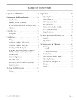
Page 3: ...unting Instructions 6 Ventilation Air 6 Statutory Regulations 7 Gas Connection 7 Electrical Connections Where Applicable 7 Installation Notes 7 Testing And Adjustment 8 Testing 8 Operation 9 Open Top...

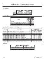
Page 4: ...4mm unit 6 open burners storage base 192 000 180 000 U36 6R 36 914mm unit 6 open burners standard oven 225 000 210 000 U36 6C 36 914mm unit 6 open burners convection oven 225 000 210 000 U60 10SS 60 1...

Page 5: ...COMMENDED FOR RESIDENTIAL INSTALLATION We suggest installation maintenance and repairs should be preformed by your local Garland US Range authorized service agency Siting The floor on which the applia...

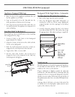
Page 6: ...TAL SCREW Backguard With High Shelves Salamander Or Cheesemelters Mounting Instructions 1 Rear of the range must be easily accessible 2 Place the backguard high shelf salamander or cheesmelter on the...

Page 7: ...an automatic isolation valve system shall be fitted which can be operated from a readily accessible position near to the exit INSTALLATION Continued At locations where the manual isolation valve is f...

Page 8: ...stat dials to OFF or lowest position All units are tested and adjusted at the factory however burners and pilots should be checked upon installation and adjusted if necessary CAUTION Gas will flow to...

Page 9: ...ain burner flame closed and but the pilot flame lit turn the control knob to the pilot position Do not push into knob 6 To shut the burner and pilot completely off turn the dial to the off symbol posi...

Page 10: ...r remove hot top sections Each burner has one pilot located at the front right side of the burner 2 Light pilots The pilot burner should be adjusted to provide for rapid ignition of the burner 3 Turn...

Page 11: ...pans should be covered whenever possible to reduce energy consumption High acid sauces such as tomato should be cooked in stainless steel rather than aluminum to avoid chemical reaction Light colored...

Page 12: ...th a non toxic oil Liquid vegetable oil or Pam spray oil WARNING DO NOT SEASON THE TOP GRATES WHILE ON THE RANGE TOP Seasoning grates on the range top over an open flame could cause a flash fire After...

Page 13: ...usually a sign of grease and dirt in the throat of the burner Remove and clean the burner and readjust the air shutter Cast Iron Top Ring Grates Cast iron top and ring rate s can be cleaned with mild...

Page 14: ...t rusting To remove discolorations use a non abrasive cleaner Before re using the griddle must be reseasoned Keep griddle drain tube to grease container clear at all times on those models without grea...

Page 15: ...Part XXXXXXX 02 07 Page 15 NOTES...

Page 16: ......

Reviews: