background image

9

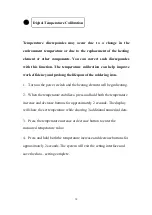
This function allows the station to comply with different user

preferences for users in different regions.

1. When the power switch is OFF, press and hold the temperature

increase button.

2. Then turn on the power switch, and the display will show “F” to

indicate the station is in Fahrenheit display mode.

3. Press the temperature increase or decrease button to select Fahrenheit

or Celsius display mode.

4. When there are no further inputs made for about 5 seconds, the

system exits the setting interface and saves the data – Setting complete.

NOTE: The stations come with a °F/°C temperature display selector

switch. Use the selector switch to select either the Fahrenheit or

Celsius display mode.

°F / °C Temperature Display

Summary of Contents for USS-SS00001

Page 1: ...1 SOLDERING STATION ESD SAFE TEMPERATURE CONTROLLED AND THERMOSTATIC ...

Page 2: ...e 5 Heat gun soldering iron and desoldering iron must be placed on the stand when not in use 6 Household and indoor use only 7 To prevent electric shock unplug before replacing the fuse or performing other service 8 Replace only with same type and rating of fuse 9 This appliance is not intended for use by persons including children with reduced physical sensory or mental capabilities or lack of ex...

Page 3: ...rviceable parts 14 To reduce the risk of fire or electric shock do not expose this product to rain or moisture Store indoors Read instruction manual before using 15 A fire may result if the appliance is not used with care therefore be careful when using the appliance in places where there are combustible materials do not apply heat to the same area for a long time do not use in presence of an expl...

Page 4: ...ble power supply cords are available and may be used if care is exercised in their use 21 If a long detachable power supply cord is used 1 The marked electrical rating of the detachable power supply cord or extension cord should be at least as great as the electrical rating of the appliance 2 The extension cord should be a grounding type3 wire 3 The longer cord should be arranged so that it will n...

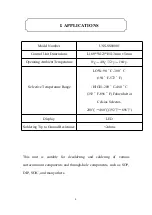
Page 5: ...P SOIC and many others Model Number USS SS00001 Control Unit Dimensions L160 W123 H113mm 5mm Operating Ambient Temperature 0 40 32 104 Selective Temperature Range LOW 90 C 300 C 194 F 572 F HIGH 200 C 480 C 392 F 896 F Fahrenheit or Celsius Selector 200 480 392 896 Display LED Soldering Tip to Ground Resistance 2ohms I APPLICATIONS ...

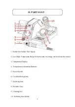
Page 6: ...Temperature Range Selector only one range can be selected at a time 3 Temperature Display 4 Temperature Adjustment Buttons 5 Power Switch 6 Cord Soldering Iron 7 Soldering Iron 8 Residues Tray 9 Cleaning Kit 10 Soldering Iron Holder II PARTS LIST ...

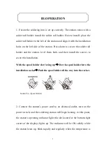
Page 7: ...rews to secure the installation With the spool holder slot facing up Slot the spool holder into the installation socket Push the spool holder all the way into the socket Socket Pin Spool Holder 2 Connect the station s power cord to an electrical outlet turn on the power switch and the soldering station will begin heating At this point the station s operating indicator light the dot located at the ...

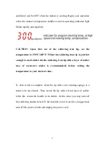
Page 8: ...ough to melt solder tin the soldering iron tip with a layer of solder use of rosin core solder is recommended before setting the temperature to your desired value 3 After work is complete clean the tip with a wet cleaning sponge or a metal wire tip cleaner Then recoat the tip with a fresh layer of solder After this return the handle to its holder At this time you may turn off the soldering station...

Page 9: ...icate the station is in Fahrenheit display mode 3 Press the temperature increase or decrease button to select Fahrenheit or Celsius display mode 4 When there are no further inputs made for about 5 seconds the system exits the setting interface and saves the data Setting complete NOTE The stations come with a F C temperature display selector switch Use the selector switch to select either the Fahre...

Page 10: ...10 to indicate the timer value of 10 minutes 3 Press the temperature increase or decrease button to set the timer value to 0 to turn off sleep mode 4 When there are no further inputs made for around 5 seconds the system exits the setting interface and saves the data Setting complete To start up from sleep mode A Shake the soldering iron a couple of times B Press any buttons on the panel C Turn off...

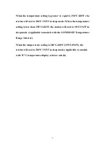
Page 11: ...mperature setting is less than 250 C 482 F the station will cool to 90 C 194 F in sleep mode Applicable to models with the LOW HIGH Temperature Range Selector When the temperature setting is 200 C 480 C 392 F 896 F the station will cool to 200 C 392 F in sleep mode Applicable to models with F C temperature display selector switch ...

Page 12: ... the heating element will begin heating 2 When the temperature stabilizes press and hold both the temperature increase and decrease buttons for approximately 2 seconds The display will show the set temperature while showing 3 additional numerical dots 3 Press the temperature increase or decrease button to enter the measured temperature value 4 Press and hold both the temperature increase and decre...

Page 13: ...ure has stabilized gently rub the soldering iron tip within the steel wool C When the oxidization is partially removed continue applying solder to the soldering iron tip while rubbing it until the tip is completely coated with solder If the tip is too severely oxidized beyond cleaning replace it with a new one 2 Do not use metal files to remove the oxidization on the soldering iron tip If the sold...

Page 14: ... or below for idling Failure to do so and leaving the soldering iron tip to idle on a high temperature setting will cause accelerated aging of the heating element and shorten the lifespan of the heating element and soldering iron tip 5 After every operation clean the soldering iron tip then tin the tip with a new layer of solder to prevent oxidization ...

Page 15: ...lace the heating element the heating element and the sensor modules 2 SLP This is an indication that the station is in sleep mode 3 When replacing the heating element take note of the original connecting order and colors of the wires which must not be connected incorrectly V TROUBLESHOOTING ...

Page 16: ...16 Contact Feel free to visit our website www ussolid com You can email us at service ussolid com You can call one of our friendly customer service representative at 1 800 209 4177 ...

Reviews: