


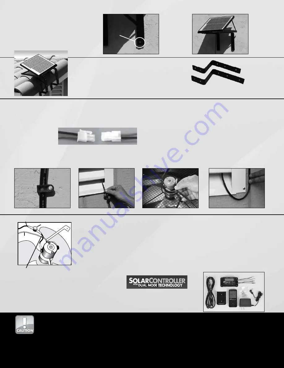
Step 2.
Depending on the material your wall is made of,
mount the assembly to the wall using appropriate
fasteners (see “Optional Hardware” on page 1 for
details).
(fig. 33 and 34)
fig. 33
fig. 34
see Optional
Hardware on
page 1
Connecting the panel to the fan:
Step 2.
Typically the wire will route through an opening in the vent or an unused
louver.
(fig. 36)
Step 3.
Connect the wires to the fan, matching the red wire to the red connector
and the black to the black connector on the motor.
(fig. 37)
Step 4.
Include a drip curve if possible when securing to the wall to prevent
water running down the wire and into the attic or crawl space.
(fig. 38)
Step 1.
Once the panel and fan are mounted, route the wire from the panel to
the fan, attaching the wire to the building appropriately. We suggest
using romex mounting clips or coaxial staple for either wood or masonry
available at your local hardware store or home builder supply.
(fig. 35)
With the optional fascia bracket kit, the panel
can be mounted directly to a fascia board.
Fascia mounting kit
Additional Accessory Available
The Solar Controller
™
has a built in thermostat and humidistat that will measure the attic
temperature and humidity and allow the fan to have extend run time in the evenings or
when no solar is available.
Visit www.ussunlight.com for additional information.
™
Thermal Switch - Optional Installation
The thermal switch will shut down the fan when the temperature drops below approximately 65˚F
and turn the fan back on when the attic temperature rises to approximately 80˚F. To install the
thermal switch, remove the
BLACK
lead from the fan motor and attach it to the thermal switch. Attach
the other lead from the thermal switch to the
BLACK
terminal on the motor. Secure the wires to the
motor bracket with tape or zip ties to prevent them from interfering with the fan blade. If you prefer
to have the fan running during cooler seasons to remove moisture from the attic, do not install the
thermal switch
(fig. 39). As an upgrade from the mechanical thermal switch, utilize the Solar
Controller with an electronic thermostat and humidistate as well as additional features.
thermal switch
red lead
(leave as is)
black lead from thermal switch
connected to black terminal on motor
original black lead from solar panel to motor
fig. 39
This solar fan will automatically start whenever the sun shines on the solar panel. Always exercise caution when in the vicinity of the fan.
To avoid accidents, use appropriate attire: safety glasses, gloves, hard hats, restraints and other appropriate equipment.
Use this product only as indicated by U.S. Sunlight Corp. Any questions on appropriate applications, call 1-877-50-USSUN.
Installation work and electrical wiring must be done by qualified person(s) in accordance with all applicable building codes and
standards, including fire requirements.
To prevent back drafting of any fuel burning equipment in the attic such as a gas furnace, sufficient air is needed for proper combustion
and exhausting of gases through the flue of fuel burning equipment. Follow the requirements made by the heating unit’s manufacturer.
Additionally, follow safety standards set fort by the National Fire Protection Association (NFPA), and the American Society for Heating,
Refrigeration and Air Conditioning Engineers (ASHRAE), and the local code authorities.
To order go to: www.ussunlight.com or call 877-55-USSUN
fig. 35
fig. 36
fig. 37
fig. 38
Some All Purpose Ventilators come equipped with the Quick Connector
mechanism. Instead of connecting the spade wires directly to the fan,
attach via the Quick Connectors.


