www.u-tec.com/lock/ul1/installation
Visit this link to watch the installation video guide
Notes
· Install and test the lock with door open to avoid being
locked out.
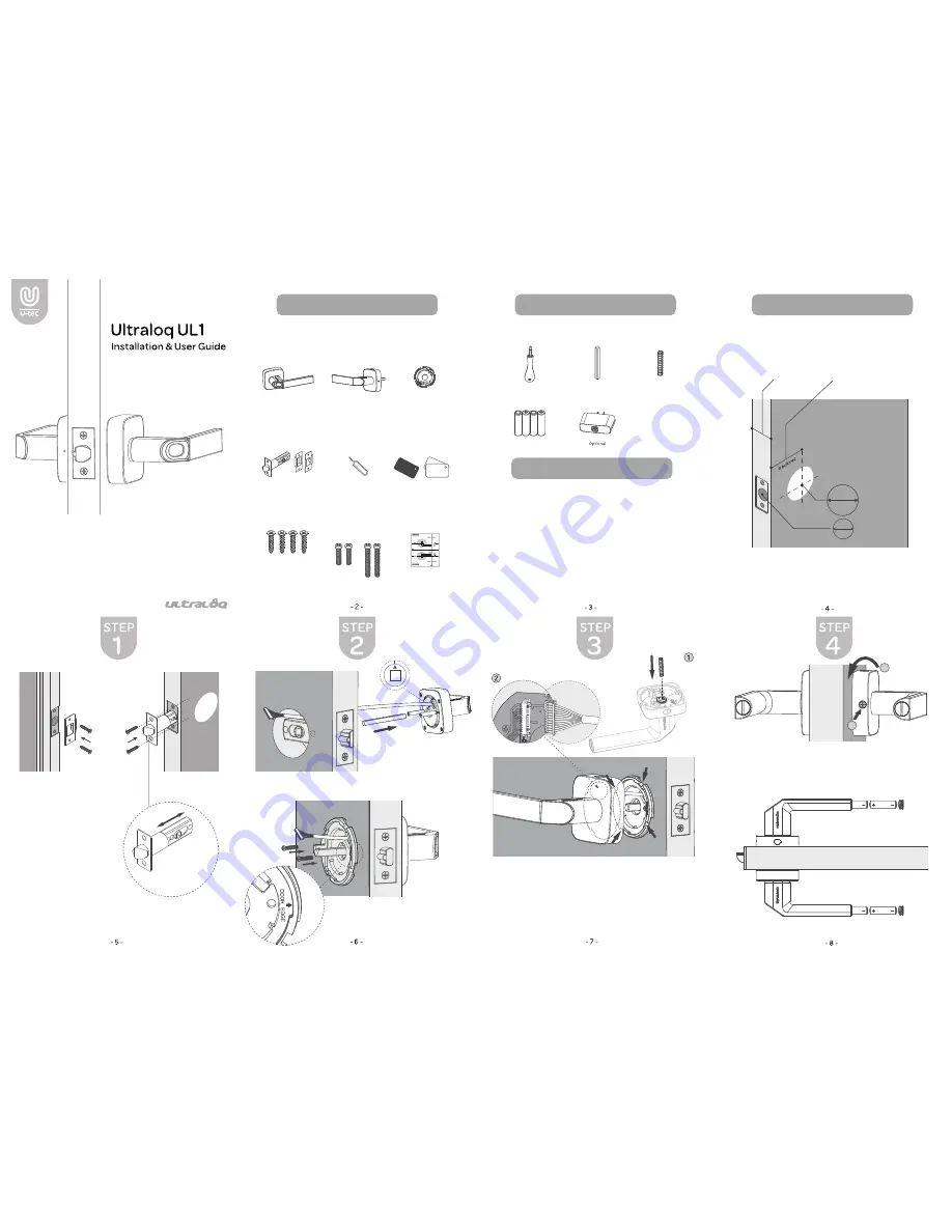
Spindle
Spring
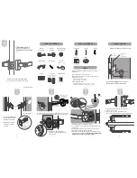
1. Install External Assembly. Plug in the Spindle, Align its two sticks with
two holes on the latch. Hole’s arrow should be directed as illustrated.
Plug in the Spindle
(V1.2)
Screwdriver
Battery
Bridge
· Opreating temperature:
External Assembly: -4 °F ~ 149 °F (-20 °C ~ 65 °C)
Internal Assembly: 14 °F ~ 131 °F (-10 °C ~ 55 °C)
· Need Help? Please contact customer support before
returning the product.
Visit www.u-tec.com/support
Email support@u-tec.com
· Please follow the instruction in order.
What’s in the Box
What’s in the Box
May not be included
for some regions
Preparing Door
2. Install Internal Mounting Plate.
Tighten 2 Screw B simultaneously to
fix the position.
Screw A
Adjust the latch
basket length
Angle faces jamb
2
3
/
8
”
2
3
/
4
”
(60 mm)
(70 mm)
Please check the door’s dimensions.
1
5
/
16
”~2
”
(33~50 mm)
1” (25 mm)
1”
25 mm
2
1
/
8
” (53 mm)
53 mm
2
1
/
8
”
If you are installing UL1 on a new door,
please refer to the Drill Template.
2
3
/
4
”
2
3
/
8
”
(70 mm)
(60 mm)
OR
Install this Spring.
1. Install the Spring into Internal Assembly.
2. Loose the side srew, and push the metal block all the way
into the slot.
3. On Internal Assembly, connect the wire to the receiver.
4. Align and insert the Spindle into the hole.
5. Match and connect the gaps between Internal Mounting
Plate and Internal Assembly.
Internal Assembly should be
tilted around 30 degrees to click the gaps.
1
2
Please note the arrow
points down for left
handed installation.
1. Turn Internal Assembly to the horizonal level.
2. Tighten the side screw.
3. Use a tool (e.g. coin) to open battery cap
(turn counterclockwise) and insert two AA batteries.
1. Insert Latch and Strike.
Please align the Latch
with the door’s edge.
2. Tighten 2 Screw A on
each side to fix the
position.
Admin
User
Internal
Assembly
External
Assembly
Internal Assembly
Mounting Plate
Key Fob
Screw A
Screw B
Drill Template
1.30 ’’~ 1.65 ’’
33 ~ 42mm
1.65 ’’~ 1.97 ’’
42 ~ 50mm
For Door Thickness Between:
Latch & Strike
Reset Needle