Solar Charge Controller 6830-122-C10/15/20
2013-06-25 2 Version 6
Step 3: Mark Holes
Use a pencil or pen to mark the four (4) mounting hole locations on the
mounting surface.
Step 4: Drill Holes
Remove the controller and drill 4mm holes in the marked locations.
Step 5: Secure Controller
Place the controller on the surface and align the mounting holes with the
drilled holes in step 4.
Secure the controller in place using the mounting screws.
3.3 Wiring
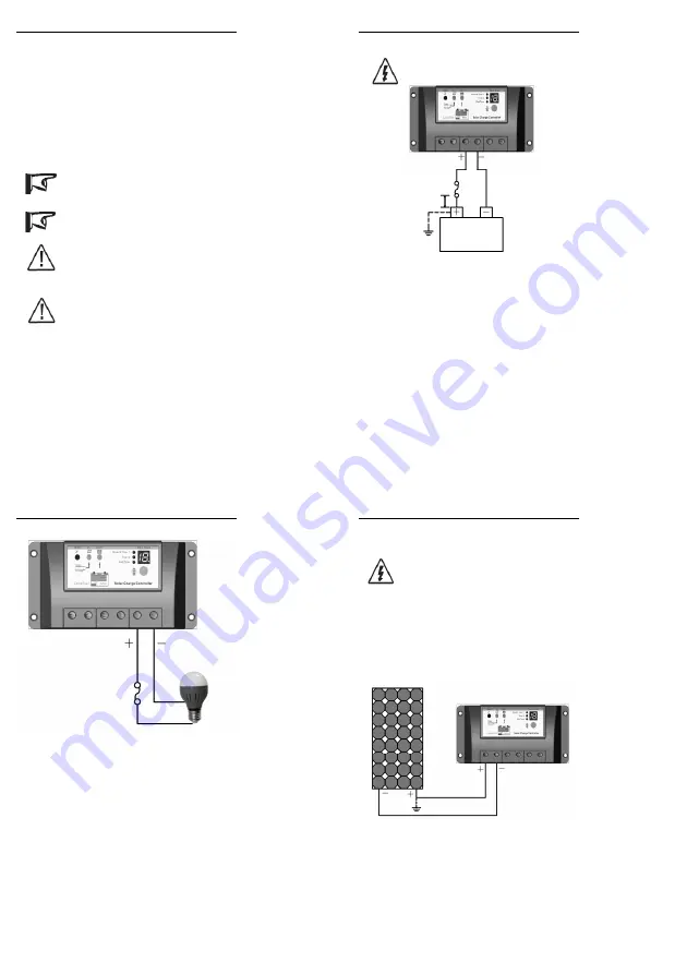
NOTE: A recommended connection order has been
provided for maximum safety during installation.
NOTE: The controller is a common positive ground
controller.
CAUTION: Don’t connect the loads with surge power
exceeding the ratings of the controller.
CAUTION: For mobile applications, be sure to secure
all wiring. Use cable clamps to prevent cables from
swaying when the vehicle is in motion. Unsecured
cables create loose and resistive connections which may
lead to excessive heating and/or fire.
Solar Charge Controller 6830-122-C10/15/20
2013-06-25 1 Version 6
Step1: Battery Wiring
WARNING: Risk of explosion or fire! Never short
circuit battery positive (+) and negative (-) or cables
Figure 3-2 Battery connecting
Before battery is connected, make sure that battery voltage is greater than 6V
so as to start up the controller. If system is 24V, make sure battery voltage is
not less than 18V. System voltage can only be automatically recognized
when controller start up for the first time.
When install fuse, make sure that the biggest distance between the fuse
holder and the positive terminal of battery is 150mm. Do not insert a fuse at
this time. Confirm the connection correct and
turn on the power.
Battery
Fuse
Battery
150mm(5.9inches)
MAX
Fuse
Solar Charge Controller 6830-122-C10/15/20
2013-06-25 1 Version 6
Step 2: Load Wiring
The controller loads can be connected to such electrical equipments as lights,
pumps, motors and others. Controller offers power to loads through the
battery voltage.
Figure 3-3 Load Wiring
Connect the positive (+) and negative (-) of loads
to controller load terminals
as shown in Figure 3-3. The load terminal may exist voltage, connect
carefully to avoid short circuit.
An in-line fuse holder should be wired in series in the load positive (+) or
negative (-) wire as show in Figure 3-3. Do not insert a fuse at this time.
Confirm the connection correct and
turn on the power.
If wiring the load connection to a load distribution panel, each load circuit
should be fused separately. The total load draw should not exceed the load
rated current of controller.
Fuse
Load
LED Bulb
Solar Charge Controller 6830-122-C10/15/20
2013-06-25 2 Version 6
Step 3: Solar wiring
WARNING: Risk of electric shock! Exercise caution
when handling solar wiring. The solar module(s) high
voltage output can cause severe shock or injury.
Be
careful operation
when installing solar wiring.
The controller can accept12V, 24V nominal off-grid solar module(s).
Grid-tie solar module(s) may be used if the open circuit voltage of solar
module doesn’t exceed the Maximum PV input voltage of the controller.
The solar module(s) work voltage must be equal to or greater than the
system voltage.
Figure 3-4 Solar wiring
Solar Module


