background image

www.totemmaker.net

Totem MiniLab

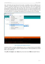
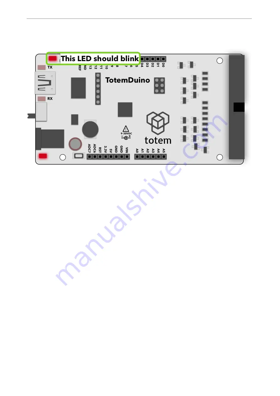
You should see a notification “Done uploading” in the bottom status bar. Now check if the 
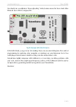
firmware does what it’s supposed to: 

!


Fig.33 Example LED blink firmware 

If the LED blinks, you got every bit working! Now you can start diving into the world of 
programming  by  exploring  other  examples  or  creating  your  own  firmwares  for  it.  You 
could plug external sensors, shields to bring even the craziest ideas to life. 

TotemDuino  tightly  integrates  with  LabBoard,  so  it  can  help  you  debug  problems  with 
your code, measure the output signal frequency, pulses, or the LabBoard could be used as 
an input device, generating needed test signals for your TotemDuino. 

Have fun! 

!

 of 

!

27

31

Summary of Contents for Totem MiniLab

Page 1: ...MiniLab User Guide Totem by UAB Aldrea ver 1 1...

Page 2: ...up 6 Measuring voltages 8 Setting output voltage 9 Digital inputs 11 Frequency meter 13 Measuring current 14 Setting programmable voltage output 16 Using pulse counter 18 Generating pulses 19 Program...

Page 3: ...ies of the MiniLab even further Who is it for Our main goal with MiniLab is to make a platform which would give an easy and approachable way for students and young makers communities to build up on us...

Page 4: ...rstly it can be used as an expansion board to the TotemDuino system offering easily accessible input and output connections and secondly it is a measuring and testing unit containing such modules as D...

Page 5: ...output pins going into LabBoard protected against over voltage or short circuit conditions No experiment could go wrong this way Expansion port a 34 pin flat cable connection connects to the LabBoard...

Page 6: ...unted in the workbench style system which allows easy access to all of available pins as well as breadboard work area Fig 3 An ongoing experiment on MiniLab workbench Powering up MiniLab comes with a...

Page 7: ...to set the voltage Voltages that are available to use are 12 V 1 0 A direct supply voltage 5 V 0 5 A regulated supply voltage shared with TotemDuino 3 3 V 0 25 A regulated supply voltage shared with...

Page 8: ...V for external signal measuring Left display is used in the LabBoard for showing currently measured voltage Currently active channel is selected with a button under the display and the current active...

Page 9: ...e close to 3 3 Volts Fig 6 Measuring one of the supply voltages Setting output voltage Using inbuilt 3 channel Digital to Analog Converter DAC allows you to output any voltage in the 0 3V range at up...

Page 10: ...t currently selected channels voltage All other inactive channels still keep the same preset voltage until it s changed by SET buttons on the side of the board Example 1 Connect the DAC1 output to the...

Page 11: ...mmaker net Totem MiniLab Fig 8 Example usage of output voltage module Digital inputs MiniLab has a two channel digital input module meant to indicate the current logic state of the signal with an LED...

Page 12: ...s 0 to 6 Volts are accepted input range A low input value 0 1 3V turns of corresponding LED where a high value 1 8V 6V turns the LED on Example 1 Connect DIG1 input with 5V output 2 Observe that DIG1...

Page 13: ...requency in 0 1 MHz range This is a special mode which temporarily disables all other modules while this one is active To enter into frequency measurement mode hold the SET button until the display cl...

Page 14: ...Code the sketch to TotemDuino 3 Connect the digital signal in the PlayMelody example D9 is used with the frequency meter input DIG1 pin 4 Observe that frequency meter measured a frequency in the Play...

Page 15: ...esistor with 0 5 V channel Fig 13 Current measuring module Experiment 1 Connect SHUNT and 0 5 V input together 2 Connect any external circuit in this example a 100 Ohm resistor is used powering it fro...

Page 16: ...mA Vin is the supply voltage for the MiniLab Vin 12 V when using an included power adaptor Output for the regulator is marked with VREG symbol The current output value in Volts is shown on the right...

Page 17: ...ogrammable regulated voltage output Example 1 Connect VREG together with 50 V input 2 Set the VREG voltage to some value 3 Observe that the 50 V input measurement follows the VREG setting Fig 16 Measu...

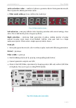
Page 18: ...ated All three displays show the number of pulses counted and up to 999999999 pulses can be registered To exit back from the pulse counter mode press STEP button Fig 17 Pulse counter module Example 1...

Page 19: ...mode all three screens turns off briefly then PPP is presented on the leftmost screen Pressing corresponding SELECT button enters into signal generation mode configuration screen This is confirmation...

Page 20: ...pulse generation configuration 2 Period setting screen numerical value parameter type Fig 22 Period entry screen Active selection value current period in s 3 Pulse width setting screen numerical value...

Page 21: ...p finite generation of pulses making number of pulses entered in pulse count menu Once finished indicate value goes back to a single underscore symbol When active a single square symbol is shown Examp...

Page 22: ...ickest way to start Firstly install Arduino IDE to your computer refer to official documentation for the Arduino IDE installation instructions which can be found here https arduino cc en Guide HomePag...

Page 23: ...ntil computer is restarted On most Linux systems driver for the TotemDuino should be included in the system already so no further steps are needed to be taken If it s missing or the device doesn t enu...

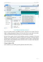
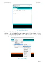
Page 24: ...st you must choose the correct board for which code will be compiled as well serial port by which the compiled firmware will be uploaded to it You can select the board by clicking Tools Board In the d...

Page 25: ...ist once you connect TotemDuino back The newly appeared port will be the port that should be used On most laptops there are no extra serial ports so you might see TotemDuino port as being the only one...

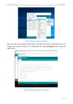
Page 26: ...cting example rmware This will open a new Arduino IDE window with the source code of that firmware Try to compile and write the firmware to TotemDuino by clicking Upload button icon with right arrow F...

Page 27: ...start diving into the world of programming by exploring other examples or creating your own firmwares for it You could plug external sensors shields to bring even the craziest ideas to life TotemDuino...

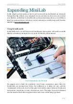
Page 28: ...Using breadboards In the MiniLab kit you will find several breadboards that together with easily accessible MiniLab connections arranged in a row can be accessed in a clean manner Fig 34 Breadboard us...

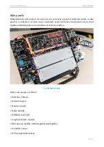
Page 29: ...most commonly used electronics blocks that can be used together with MiniLab to even further extends it s abilities Fig 35 Side panels In the side panels you ll find Switches buttons Potentiometers R...

Page 30: ...to build a connected system as an example you could program it to control the DC motor by rotating the potentiometer and displaying the current value on the OLED screen or making a sound activated re...

Page 31: ...adboards you can easily experiment with new sensors drivers and many more electronic devices and measure or supply your own generated signals from LabBoard We hope that you ll never run out of inspira...

Reviews: