background image

14

Revised 03/15

MCB

Crossflow Dust Collector

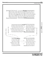
When both filters are in place, lift the left handle 

(pivoting counter-clockwise) into a horizontal position. 

Next, lift the right handle (pivoting clockwise) taking 

care that the retaining clip (on the backside of the 

handle) grabs the left handle. Finally, lift the right 

handle above the left handle retaining clip and rest in a 

horizontal position as shown in Figure c.

Figure c. 

The filters should be firmly compressed against the tube 

sheet and ready for operation.

7.2 Dust Drawer Removal

1.  As the cartridges are cleaned, dust will collect in 

drawers located at the base of the module. Handles 

are provided on the front and rear of each drawer for 

easy handling.

2.  When the drawers are full, simply remove from unit 

and empty contents.

3.  To replace the drawers, align the “V-notch” (on the 

bottom of the drawer) with the tracks on the models 

base panel and slide the drawer in place.

7.3  SERVICING THE DIRECT DRIVE MOTOR 

AND BLOWER WHEEL

Periodically inspect the fan blades to ensure proper  

fan life. Grease the motor every 2,000 hours with high 

grade ball and roller bearing grease. The recommended 

grease is Chevron SRI#2.
Periodically inspect the fan wheel coupling mounting 

bolts for tightness. Re-tighten as necessary to ensure 

the fan wheel does not loosen and come in contact  

with and rub the inlet bell.


!

  C A U T I O N

Drawers may be heavy due to weight of  

collected dust.

2.  Replacement cartridge filters should be ordered 

when the differential pressure across the filter is 

consistently above 5" w.g. (127 mmAq) or system 

airflow is inadequate. To order filters contact UAS  

at 888-515-8800.

3. To remove the filters:

Lift the right handle out of the retaining clip as shown in 

Figure a.

Figure a. 

Once the right handle has cleared the retaining clip, 

lower both handles to a vertical position as shown in 

Figure b.

Figure b. 

Using the tab on the underside of the filter end cap, 

slide the filter out of the unit (also shown in Figure 2). 

Once the front filter is removed, reach back into the 

cabinet and remove the rear filter in the same manner.
4. To replace filters:
Place the Protura® cartridge filter with the square end 

cap resting on the locking bar rails. Slide the rear filter 

until running in to backstop at rear of cabinet. Place 

front filter on rails and slide into cabinet until filter 

touches rear filter.


!

  C A U T I O N

The filter may be heavy due to the weight of the 

collected dust.

Summary of Contents for CLARCOR MCB 06-01-S

Page 1: ...Cross Ventilation Cartridge Dust Collector l MCB Series OWNER S MANUAL ...

Page 2: ...mation available when contacting UAS UAS ORDER __________________________________________________________ UNIT MODEL _ ________________________________________________________ UNIT SERIAL _ ________________________________________________________ CARTRIDGE FILTER PART ______________________________________________ SYSTEM ACCESSORIES _________________________________________________________________...

Page 3: ... 5 1 1 Digital Pulse Monitor DPM Panel Installation 10 5 1 2 Digital Pulse Control DPC Panel Installation 10 5 1 3 Final Connections For All Gauge Options 10 5 2 Electrical Connections For Booth Lights 10 5 3 Solenoid Valve Enclosure Wiring 10 6 OPERATION 10 6 1 Start Up 10 6 2 Operating Adjustments 12 6 2 1 Digital Pulse Monitor Panel DPM 12 6 2 2 Digital Pulse Control Panel DPC 12 7 SERVICE 12 7...

Page 4: ...accumulation which may result in flash over or fire damage The MCB system should not be used for support of personnel or material Operate only in safe and serviceable condition DANGER WARNING CAUTION C A U T I O N This is the safety alert symbol This symbol alerts you to potential hazards that can kill or hurt you and others All safety messages will follow the safety alert symbol and the word DANG...

Page 5: ...eaning in the work environment or as part of your manufacturing process As you review this manual refer to Figure 1 and 2 for assistance in locating unit parts 2 3 AIR FILTERING OPERATION During the air filtering operation contaminated air enters the Mcb dust collector through the door louvers The inlet louvers allows heavier particles to fall into the dust storage drawer The contaminated air then...

Page 6: ...2 Revised 03 15 MCB Crossflow Dust Collector Figure 1 MCB Operation Detail 44 10343 0001 ...

Page 7: ...3 Revised 03 15 MCB Crossflow Dust Collector Figure 2 Typical MCB Dust Collector With Booth Enclosure Installation 44 10344 0003 ...

Page 8: ... to be installed the modules need to be spaced with a 1 gap between side panels A UAS supplied trim strip will bridge the gap between the units 3 To install the trim strip remove all fasteners on the front panel of the adjoining corner from both cabinets Locate the trim strip so as to match the cabinet bolt pattern and re fasten the screws Repeat as necessary for additional modules 4 3 1 Compresse...

Page 9: ...5 Revised 03 15 MCB Crossflow Dust Collector Figure 3 MCB Installation Detail 44 10360 0001 ...

Page 10: ...t wall bracket only has one See Figure 5 2 On the inlet side of all modules remove the top row of fasteners excluding the ones holding the trim strip in place Locate the top panel support bracket using the fasteners attach to each module 3 Starting at a corner lay the wall base channel in place squared to the unit and against the vertical corner channel Sections of the base channel should fit tigh...

Page 11: ...7 Revised 03 15 MCB Crossflow Dust Collector Figure 4 Motor Installation Diagram 44 10342 0001 ...

Page 12: ...8 Revised 03 15 MCB Crossflow Dust Collector Figure 5 MCB Booth Assembly 44 10361 0001 ...

Page 13: ...9 Revised 03 15 MCB Crossflow Dust Collector Figure 6 Booth Panel Interlock Connection ...

Page 14: ...ol DPC panel remove it from the box Instructions for mounting and connecting the panel are available in the DPM DPC Installation and Owner s Manual The panel should be installed within close proximity of the unit as shown in Figure 7 The DPM DPC panel requires field electrical connections 5 1 3 FINAL CONNECTIONS FOR ALL GAUGE OPTIONS For all pulse control panels connect the black plastic pressure ...

Page 15: ...11 Revised 03 15 MCB Crossflow Dust Collector Figure 7 MCB Pressure Gauge Installation 44 10350 0001 ...

Page 16: ... a pulse If the delivery capability of your compressed air source cannot return the manifold pressure to above 90 PSIG during the Pulse Delay factory set at 10 sec interval adjust the pulse delay at the timerboard and monitor the pressure A longer interval will raise the operating pressure which is the pulse delay Adjust from position 2 or position 3 on the timerboard Allow sufficient time for the...

Page 17: ...13 Revised 03 15 MCB Crossflow Dust Collector Figure 8 Solenoid Wiring to Pulse Controls 61 10017 0001 REV B ...

Page 18: ...ng grease The recommended grease is Chevron SRI 2 Periodically inspect the fan wheel coupling mounting bolts for tightness Re tighten as necessary to ensure the fan wheel does not loosen and come in contact with and rub the inlet bell C A U T I O N Drawers may be heavy due to weight of collected dust 2 Replacement cartridge filters should be ordered when the differential pressure across the filter...

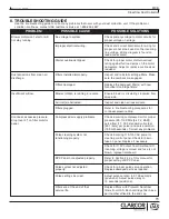
Page 19: ...l excessive pressure drop over 5 on filter monitor panel Compressed air supply problems Check incoming compressed air for proper pressure 90 110 PSIG 6 4 7 2 BAR pulse flow 1 7 SCF standard cubic feet 48 1 liters per pulse and pulse duration 100 milli seconds Correct any problems Pulse cleaning system not functioning properly Check incoming 110 115 VAC power to cleaning control panel Check for blo...

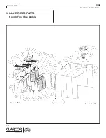
Page 20: ...16 Revised 03 15 MCB Crossflow Dust Collector 9 ILLUSTRATED PARTS 6 and 9 Foot Wide Module ...

Page 21: ...ER BOARD Not Shown SOLENOID ENCLOSURE 4 POSITION SOLENOID ENCLOSURE 6 POSITION SOLENOID REPAIR KIT Not Shown SOLENOID VALVE REPLACEMENT Not Shown LIGHTING FIXTURE 2 BULB FLUORESCENT FINISHING PLUG 2 1 4 DIA SCREW HEX WASHER 5 16 18 x 3 4 LG SWAGEFORM BLOWER WHEEL SIZE SPECIFIC TO UNIT BLOWER INLET CONE CONSULT UAS CARTRIDGE FILTER VIEW LABEL ON END OF FILTER AND CONSULT UAS 1 4 NYLON TUBING FITTIN...

Page 22: ...18 Revised 03 15 MCB Crossflow Dust Collector 11 ILLUSTRATED PARTS 3 Foot Wide Module ...

Page 23: ...OSURE 2 POSITION SOLENOID REPAIR KIT Not Shown SOLENOID VALVE REPLACEMENT Not Shown FINISHING PLUG 2 1 4 DIA SCREW HEX WASHER 5 16 18 x 3 4 LG SWAGEFORM BLOWER WHEEL BLOWER INLET CONE CARTRIDGE FILTER VIEW LABEL ON END OF FILTER AND CONSULT UAS TUBE FITTING 90 DEG ELBOW I 8 NPT MALE x 1 4 TUBE PLUG PIPE 1 NPT BLACK IRON LATCH HANDLE INLET LOUVER DOOR BLOWER ASSEMBLY SEALANT GORE TEX CONSULT UAS 02...

Page 24: ...authorized repairs or modifications UAS makes no warranty as to goods manufactured or supplied by others This warranty is subject to any limitations in UAS quotation and may not be modified except by a written instrument signed by the President or Vice President of Sales of UAS THIS WARRANTY IS EXCLUSIVE AND IN LIEU OF ALL OTHER WARRANTIES WHETHER WRITTEN ORALOR IMPLIED INCLUDINGANYIMPLIED WARRANT...

Reviews: