4
revised 09/09
Smog-Hog
SG Series Model
4.2 COLUMN OR WALL MOUNTING
units may be suspended from cantilevered supports
on walls or columns. SG-2 and SG-4S units may be
mounted against columns but should extend at least
24” from walls in keeping with good airflow practice.
SG-4T units require 36” clearance from walls and
columns for blower compartment access.
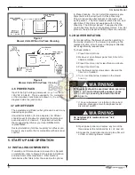
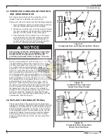
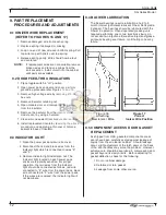
Prior to installation, refer to specifications in figures 1,
2 and 3. Note mounting and clearance requirements
and allow for proper plumbing and electrical access.
allow at least 36” for door swing and component access
on the door side of the unit. All SG models require 18”
clearance from overhead obstructions for access to
electrical junction boxes.
4. INSTALLATION
carefully remove the unit from the shipping con-
tainer, inspecting for shipping damage. for ease of
installation, open access door and remove unicells and
filters from the cabinet.
Units suspended from the ceiling require 1/2” threaded
rods installed in top corners of the units. See figure 2
for mounting hole locations for all models. additional
support should be used for auxiliary equipment or
ducting. the SG should not be used for support of
personnel or material.
reinstall the components which were removed ear lier
to facilitate mounting the unit.
4.1 CEILING MOUNTING
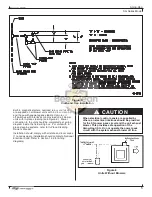
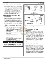
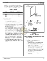
SG units are designed for suspended mounting,
using 1/2” all-thread rod as shown in figure 4.
customer should take care to ensure that roof
trusses are adequate to support unit weight and
support members. in figure 4, angle iron cross
members are secured between roof trusses.
turnbuckles greatly simplify rod installation.
rod length should be kept to a minimum
36” preferred). all SG units have cross-broken
sheet metal sumps with drains centered under the
collection section.
Model
Weight (lbs)
SG-2X
250
SG-2X-a
275
SG-2
400
SG-2-a
450
SG-4X
375
SG-4X-a
400
SG-4S
750
SG-4S-a
800
SG-4t
825
SG-4t-a
875
SG-6X
700
SG-6S
1,870
SG-6S-a
1,960
4.3 BOTTOM SUPPORTS
units may be supported from underneath, provided
care is taken to assure good drain connection and
leak-free sumps.
4.4 DRAINS
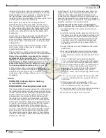
all SG units are supplied with 1 1/2” fPt drains. if dry
material is to be collected and in-place cleaning is not
supplied, then drain connection(s) should be plugged.
If in-place cleaning is supplied, or a liquid is collected
within the SG unit, refer to figure 5 for drain and drain
trap installation.
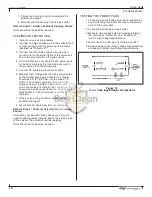
4.5 ELECTRICAL CONNECTIONS
all SG units are provided with terminal blocks in a
top-mounted electrical box for incoming power
connections. Units with blowers have box- mounted
step-down transformers to supply re quired 115 volts to
power packs. Units without blowers are equipped for
115 volt supply only (see figure 6).
Figure 4
Typical Ceiling Mount
Model SG-2
Figure 3
SG Unit Weights

