7
revised 09/09
Smog-Hog
SG Series Model
5.3 BLOWER CURRENT MEASUREMENT
using an ammeter measure the current amperage of
the blower motor. The measurement should not exceed
the full load ampere (fLa) rating identified on the
blower motor nameplate. If the amperage is excessive,
perform the following: check overload relay for proper
setting per motor fLa, and measure blower rpm.
Blower speed can be measured with a tachometer.
call uaS customer Service for blower rpm
specification. The serial number of the unit is required
to determine the blower rpm factory setting.
5.4 MOTOR VARIABLE PITCH PULLEY
ADjUSTMENT
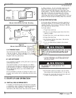
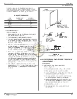
increasing blower speed (rPM) will increase airflow
(cfM) and current (amps). to increase speed, close
the variable pitch pulley (from “normal,” as in figure
9a, toward “full closed,” as in figure 9B). Decreasing
blower speed (rPM) will decrease airflow and current.
to decrease speed, open the variable pitch pulley
(from “normal,” as in figure 9a, toward “full open,” as
in Figure 9C). Five turns open (T.O.) is the maximum
setting.
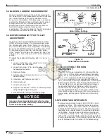
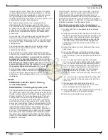
to adjust the variable pitch pulley, refer to figures 9
and 10.
1. Loosen motor base nuts, adjust motor slide base
and remove the drive belt.
2. Loosen set screw “a” to clear the drive key
between pulley halves.
3. remove the key.
4. adjust pulley in increments of one turn to the
desired setting.
5. install key and tighten set screw “a.”
6. install drive belt.
7. Loosen set screw “B.”
8. align belt centerlines of motor and blower pulleys
using straight edge and square.
9. Set belt tension using a belt tension gage.
Improper blower speeds adversely affect system
performance. Contact the factory before adjusting
motor variable pulley setting.
5.5 BLOWER BELT TENSION
ADjUSTMENT
the drive belt tension adjustment is critical within the
first 24 hours of the system exhaust blower operation.
During this 24 hour period the initial stretch of the belt
occurs which requires a belt tension adjustment. If
this tension adjustment is not completed the belt will
wear prematurely, requiring a replacement. A drive belt
tension gage should be used for adjusting belt tension.
if fan belt tension is not per specifications set tension
by adjusting the motor slide base, refer to figure10.
Loosen four bolts holding the motor to the base and
turn the adjustment bolt(s) on the base. check with a
steel straight edge to make sure that motor pulley and
blower pulley is still aligned. tighten motor mounting
bolts.
5.6 POWER PACK OPERATION
the power pack voltage range is 90 to 130 ac, 60 Hz,
supplied by others. if the electrical panel is supplied
by others the power pack circuit should be electrically
interlocked with the blower circuit. the SG unit will be
operating in an unsafe mode if an electrical interlock is
not installed. a power pack enclosure wiring diagram
is illustrated in Section 12.2. the power pack indicator
light on the unit is illuminated when high voltage output
is within specifications. if the indicator light is flashing or
fails to illuminate refer to Section 10 troubleshooting.
!
NOTICE
Figure 9
Motor Pulley Settings
Figure 10
Motor/Blower Schematic
9
9
9

