16
revised 09/09
Smog-Hog
SG Series Model
STEP 2
PROBLEM: Indicator light is flashing.
PROCEDURE: Checking the unicell
components
Do not proceed with step (2) until step (1) is completed.
the following steps are the process of elimination in
identifying the problems to the ionizer/collector cell
circuit.
there are four conditions which could occur with a
flashing indicator light.
1. the high voltages are below specifications to the
ionizer and or the collector cell circuit(s).
2. there is an arcing condition to the ionizer and or
collector cell circuit(s).
3. there is a dead short condition.
4. the power pack has failed. refer to step 1.
(a)
Place the toggle switch in the off position, and
open power pack lid door. Disconnect high voltage
wire #8 to the ionizer connector with high voltage wire
#7 (collector) connected on the power pack and place
toggle switch in the on position and engage interlock
switch. the indicator light should be illuminated. if so,
the cell circuit is operational proceed to (b). if indicator
light is flashing perform the following:
• Place toggle switch in the off position, open
component door, and remove the unicell(s).
• Place toggle switch in the on position, and engage
interlock switch. the indicator light should be
illuminated. if the indicator light is illuminated the
problem is within the collector cell section. if the
indicator light is flashing the problem is the high
voltage door feed through insulator (dirty, cracked,
carbon tracking) and or the high voltage wire
(broken wire or wire insulation has deteriorated
causing a dead short condition).
Parts should be replaced as required.
inspect the unicell(s) for the following:
COLLECTOR CELL CONDITIONS CAUSING FAILURE
• Dirty collector cell(s) (contaminant build up bridging
the cell plates and or on cell triangular insulators)
requiring manual cleaning.
• “Wet” collector cell(s), not properly dried after a
wash cycle or manual cleaning procedure, use
compressed air to accelerate the drying time.
• Deformed collector cell contact springs contacting a
“grounded surface”.
• Misaligned contact springs (contacting a grounded
surface) between the outer and inner most cells if
module is equipped with two unicells and or at high
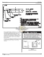
voltage feed through insulators. refer to figure 20.
• Bent cell plate(s) contacting the opposing cell
plate(s).
• Warped cell plate(s) which could be due to high
duct operating temperature, consult uaS.
• Carbon tracking to the cell high voltage feed
through insulator and or cell triangular insulators,
imbedded black streak which cannot be removed
by cleaning (replace insulator.)
• Surface oxidation to unicell component requiring
a replacement.
• Unicell is structurally weak, loose steel rivets,
deterioration to cell plate spacers or paper thin cell
plates due to utilizing the improper detergent.
Parts should be replaced as required, install unicell(s).
Sometimes a flashing indicator light will clear itself
by removing the unicell(s) from the module and then
installing the unicell(s) back into the module.
the Bench test Procedure will determine which
unicell(s) are causing a flashing indicator light, refer to
Section 10.3.
Place toggle switch in the off position; connect all wires
which have been disconnected and install unicell(s).
(b)
indicator light is illuminated with the high voltage
wire #7 connected to the collector cell connector on the
power pack. Place toggle switch in the off position and
connect high voltage wire #8 to the ionizer connector
on the power pack. Place the toggle switch to the on
position and engage the interlock switch.
the indicator light should be illuminated? if so, the
unicell(s) are operational. if the indicator light is flashing
perform the following:
• Place power in the off position, open the
component door, and remove unicell(s).
• Place toggle switch in the on position and engage
interlock switch. if the indicator light is illuminated
the problem is within the ionizer section. if the
indicator light is flashing the problem is the high
voltage door feed through insulator (dirty, cracked,
carbon tracking) and or the hv wire (broken wire
or wire insulation has deteriorated causing a dead
short condition).
Parts should be replaced as required, install unicell(s).
inspect the unicell(s) for the following:
IONIzER CONDITIONS CAUSING FAILURE
• Dirty ionizer(s) (contaminant build up) requiring
manual cleaning.
• “Wet” ionizer(s), not properly dried after a
wash cycle or manual cleaning procedure, use
compressed air to accelerate the drying time.
• Deformed ionizer contact springs contacting a
“grounded surface.”
• Misaligned contact springs (contacting a grounded
surface) between the outer and inner most ionizer,
if module is equipped with two unicells, or at the
ionizer high voltage feed through insulator. refer
to figure 20.


