18
revised 09/09
Smog-Hog
SG Series Model
teStinG tHe PoWer PacK
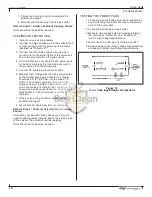
1. connect ac cable to the power pack connectors 5
and 6 with the ground wire secured to the ground
stud on the power pack.
2. connect ac cable plug to wall outlet.
3. Measure high voltage with high voltage probe at
the connectors “ionizer #8” and “collector #7”,
refer to high voltage specifications.
4. Disconnect ac cable plug from the wall outlet.
5. replace power pack if high voltage measurements
are above or below high voltage specifications.
7. if there is an arcing condition, determine the
problem and repair.
8. Disconnect ac cable plug from the wall outlet.
Refer to Step 2 “Ionizer Conditions Causing Failure”
Parts should be replaced as required.
teStinG coLLector ceLL
1. Select one unicell to be tested.
2. connect one high voltage wire to the collector cell
contact spring and to the power pack connector
identified as “collector #7”.
3. connect the other high voltage wire (use as a
ground wire) to the metal frame of the unicell cell
and to the ground stud on the power pack.
4. ac cable should be connected to the power pack
connectors 5 and 6 with ground wire secured to
the ground stud on the power pack.
5. connect ac cable plug to the wall outlet.
6. Measure high voltage with the high voltage probe
at the contact spring cell. collector cell voltage
should be 5.0 to 7.5 KVDC, not to exceed 7.5
KVDc. the collector cell will not maintain high
voltages above 7.5 KVDc. the collector cell
will continuously arc. usually this condition is
caused by a power pack above the “High Voltage
Specifications.” the power pack should be
replaced.
7. if there is an arcing condition, determine the
problem and repair.
8. Disconnect ac cable plug from the wall outlet.
Refer to Step 2 “Collector Cell Conditions Causing
Failure”.
unicell may not be within high voltage specifications,
even though manually cleaned, due to the service “age”
of the unicell. the unicell should be replaced.
Parts should be replaced as required.
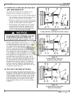
Figure 19
Power Pack Input/Output Connections


