background image

18 | Art.-nr.: 

616711-A

Ubifl ux Vigor W225  |  19

5.5.3 Connecting the eBus connector

For connecting an eBus connector, the 2-pole detachable (green) connector X17 is located at the rear of 
the display cap (  Exploded view of appliance page 10). The eBus protocol may for instance be used to 
connect the Air Control (  Connecting Air Control page 42). Because of polarity sensitivity, always connect 
contacts correctly; the appliance will not work if these contacts have been interchanged! 

The following functions can also be connected to the eBUS connector: the optionally available CO2 sensor(s) 
( connecting CO2 sensor(s) page 44) or an additional eBUS pre-heater ( connecting pre-heater page 
47) or post-heater ( connecting post-heater page 46).

5.5.4 24 volt connection

On the X16 & X18 connector of the basic pcb, 24 volt is available. Connector X-16 is for 24 volt connection of 
the optional Plus pcb. For position connection (black) connector X16 & X18 (   Electrical diagram page 35). 

Maximum current reduction at plug X16 and X18 is 5 VA per connection.

5.5.5 Connecting humidity sensor

The optional humidity sensor has to be connected onto the the X07 connection of the basic pcb. For this, 
use the cable supplied with the humidity sensor. In order to connect the humidity sensor, the plastic cover 
above the control has to be taken off , after which the X07 connection is accessible.

For connecting the humidity sensor, see   Connecting humidity sensor page 43.

5.5.6 Connection external Bus

The Modbus/ external bus (red) connector X15 can for example be used for coupling appliances (  Coupling 
appliances using external Bus page 19).

The function of this connector can be adjusted using step number 14.1 to 14.4 in the settings menu.

If the appliance is fi tted with a Plus pcb, then this red connector X15 is also in use for connecting the Plus 
pcb; several cables then have to be connected onto this connector X15.

5.5.7 Connecting "signal output” connector

The blue 2-pole screw connector X19 (   Electrical diagram page 35). This connection is used to give a 
fi lter message or fault message.

If a fi lter or fault message is given in the appliance a contact is closed at connection X19. The operation of 
this is set by following step number 16.1.

5.5.8 ModBus Connection

The appliance can be connected with a ModBus system such as a building management system.

Using the (red) 3-pole connector X15 (or with the Plus version the red connector X06 on the UWA2-E 
pcb) a connection can be made between the appliance and the ModBus system; (  Electrical diagram 
page 35) for the right connection. 

For the correct setting of the jumpers X12, X121 & X122 see the explanation given with electrical diagram 
(  Electrical diagram page 35); for more information and the correct modBus settings see the separate 
Modbus manual on the website!

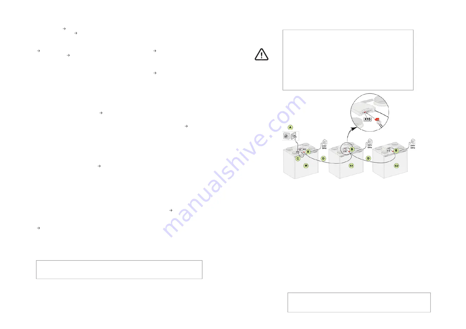
5.5.9 Coupling appliances using external Bus

Note:

 When ModBus is active, the ventilation mode cannot be changed using the display or, if 

applicable, the connected multiple switch! Also any connected humidity sensor will not function.

Note: 

Any accessory such as moisture sensor, position switch, extension board or any 

eBus device must be connected to the Ubifl ux Vigor W225 master appliance only.

Important: 

Because of polarity sensitivity, always connect the external Bus contacts X15-
1 with one another, and the contacts X15-2 and the contacts X15-3 with one 
another. Never connect X15-1, X15-2 or X15-3 with one another!

Comment:

 If a Plus pcb has been installed; several cables would have to be 

connected onto the X-15 connector.

Note: 

When the total length of the external Bus cables is longer than 10 m, then 

use a twisted-pair cable for connection X15-2 & X15-3 (a twisted pair cable is 
also preferred with shorter lengths)!

A = Multiple switch
B = 3-pole connector red
C = Modular cable
D = 3-core low voltage cable
M = Master appliance (For example a Ubifl ux Vigor appliance type 4-0)
S1 / S2 = Slave appliances (For example a Ubifl ux Vigor appliance type 4-0); connect max. 
of 10 appliances via externalBus

All Ubifl ux Vigor W225 appliances have the same air fl ow rate as the appliance that is set 
as "Master". The fault messages of 

all

 appliances are shown on the display of the master 

appliance. When using a Air Control or the Home, always connect this to the Master.

After connecting the cables confi gure each Ubifl ux Vigor W225 appliance:

|

Enable "externalBus" in menu 14.1 "Type of Bus connection" where shortly after the 
network symbol appears.

|

Confi gure each slave in menu 8.1 "Appliance setting slave 1, slave 2 etc where shortly 
after the M symbol appears on the master appliance and S1, S2 symbol on slave 
appliances

|

Power down and up all appliances

For M (master):

Step no. 8.1 - Master 
Step no. 14.1 - externalBus

For S1 (Slave 1):

Step no. 8.1 - Slave
Step no. 14.1 - externalBus

For S2 (Slave 2):

Step no. 8.1 - Slave
Step no. 14.1 - externalBus

Summary of Contents for Ubiflux Vigor W225

Page 1: ...INSTALLATION REGULATIONS Ubiflux Vigor W225 English...

Page 2: ...ave received clear instructions on the safe use of the appliance and understand the possible dangers on the condition that the appliance has been placed and installed in the normal position for use Ch...

Page 3: ...Maintenance siphon 31 9 3 Maintenance installer 32 10 Electrical diagram 35 11 Electrical connections accessories 37 11 1 Connecting position switch 37 11 1 1 Connecting position switch with filter in...

Page 4: ...dimensions It is possible however to later equip the appliance with a Plus pcb The appliance comes ready to plug in with a 230 V mains plug 3 Version 3 1 Technical information Ubiflux Vigor W225 Plus...

Page 5: ...a right hand version the warm connections 1 3 are on the right hand side of the appliance Left hand version Right hand version All dimensions in millimeters Diameter of all collars is 125 mm All dimen...

Page 6: ...r example be chosen but control is also possible with the Air Control Connecting Air Control page 42 CO2 sensor s Connecting CO sensor s page 43 a humidity sensor Connecting humidity sensor page 45 or...

Page 7: ...ions regarding the ventilation of homes and residential Safety provisions for low voltage installations The regulations for connecting indoor plumbing in homes and residential buildings Any additional...

Page 8: ...2 not supplied with the appliance so that the siphon can be cleaned easily in the future The condensate discharge can be connected for example with a straight or angled connection with gasket Slide th...

Page 9: ...of 5 m s in the main ducts and 3 5 m s in the branches The location of the discharge of the mechanical ventilation air and the sewer stack vent must be chosen to prevent noise nuisance The location of...

Page 10: ...building management system Using the red 3 pole connector X15 or with the Plus version the red connector X06 on the UWA2 E pcb a connection can be made between the appliance and the ModBus system Ele...

Page 11: ...sed to operate the appliance and to provide the user with information about the status of the appliance When the mains power is switched on the software version is first shown the main screen is then...

Page 12: ...emand driven ventilation Break contact active or make contact active This appliance is set as Master appliance if a number of appliances are connected cascade Appliance is set as Slave appliance maxim...

Page 13: ...e to reset the correct language time and date in setting menu 4 The appliance will then operate immediately after this according to the mode of the multiple switch If no multiple switch is connected t...

Page 14: ...y Codes Non locking fault When the appliance detects a non locking fault it will keep running limitedly The permanently lighted display shows the fault symbol Press the fault symbol for an explanation...

Page 15: ...available Take voltage from appliance Replace UWA2 B pcb Fault is automatically reset when voltage is again put back on appliance E1155 E2000 Touchscreen fault general fault message Fault codes only...

Page 16: ...Home button and the display then returns to the main screen the filter message is reset and the filter message now disappears Comment If the filter wizard is opened in order to replace the filter whil...

Page 17: ...supply by pulling out the plug Open the filter door 2 Remove the two filters 3 Remove the front cover 4 Remove the heat exchanger Be careful not to damage the foam parts in the appliance 5 Wash the h...

Page 18: ...y back into the appliance when doing so take care that the EPS parts and rails in the appliance are not damaged which could otherwise leads to internal leaks in the appliance Take care when returning...

Page 19: ...ervice activities then a wizard starts up automatically follow the instructions on the display for the correct connection of the fan cables Basic print X15 externalBus ModBus X16 24V X17 eBus X18 24V...

Page 20: ...or wireless remote control C Transmitter with 4 settings for example kitchen D Transmitter with 2 settings for example bathroom E Any additional 2 or 4 settings transmitters maximum of 6 transmitters...

Page 21: ...on the type of modular cable used 11 1 4 Connecting extra multiple switch with filter indication A Ubiflux Vigor appliance For example a Ubiflux Vigor appliance type 4 0 B1 Multiple switch with filte...

Page 22: ...ector E Position green eBus connector to rear of control 1 Ubiflux Vigor appliance 2 Basis pcb 3 Cover 4 The cable that comes with RH cable 5 RH humidity sensor 6 Duct from dwelling A Ubiflux Vigor ap...

Page 23: ...ir quality Matching the ventilation need with demand driven ventilation can be done in two different ways namely based on CO2 measurements or based on a time program Two different sets are available f...

Page 24: ...ppliance 4 Temperature sensor 5 PCB type UVP1 6 Airflow direction 7 Dipswitch setting postheater 1 Heating coil 2 Maximum safety with manual reset 3 2 pole eBus connection X17 on appliance 4 Temperatu...

Page 25: ...g on and off Off On off 11 2 Switch temperature 1 5 C 0 0 C 10 0 C 11 3 Switch temperature 2 25 C 15 0 C 40 0 C 11 4 Mode valve 10 volt control Closed Open Closed 11 5 Valve control Relay output 1 Rel...

Page 26: ...pcb UWA2 E 0883246 9 Mains plug and cable 230 V 0883261 10 Internal preheater incl maximum security 11 Temperature sensor NTC 10K 0704637 12 Condensation discharge 0883264 13 Cable set 0883265 14 Cab...

Page 27: ...pass temperature from outside 10 C 7 C 15 C 2 4 Bypass hysteresis 2 C 0 C 5 C 2 5 Mode Bypass boost Uit Aan Uit 2 6 Fan setting selection Bypass boost 3 0 1 2 of 3 3 Frost protection 3 1 Frost tempera...

Page 28: ...iance with Plus pcb Step no Description Factory settings Setting range Comment 9 Switch contacts 9 1 Make or break contact 1 Make Make Break 9 2 Switch contact control 1 Off Off On Meets Bypass condit...

Page 29: ...e valve 24 volt control Closed Open Dicht 11 5 Valve control Relay output 1 Relay output 1 Relay output 2 Analogue output 1 Analogue output 2 14 Conformity declaration Conformity declaration Manufactu...

Page 30: ...heat exchanger Recuperative plastic cross counterflow heat exchanger Thermal efficiency 92 Maximum flow rate 225 m h Maximum rated power 165 W Sound power level Lwa 39 dB A Reference flow rate 158 m h...

Page 31: ...ng Sustainable materials are used in the manufacture of this appliance The packaging should be disposed of in a responsible manner and in accordance with governmental regulations 60 Art nr 616711 A Ub...

Page 32: ...Jan Samijnstraat 9 B 9050 Gentbrugge Tel 32 0 9 237 11 00 www ubbink be info ubbink be Ubbink UK Ltd Unit 2 Redbourne Park Liliput Road Brackmills Ind Est Northampton NN4 7DT T 44 0 1604 433000 F 44 0...

Reviews: