43
Ubiflux W300(+) / W400(+) / W450(+)
Ubiflux W300(+) / W400(+) W450(+)
44
43
Ubiflux W300(+) / W400(+) / W450(+)
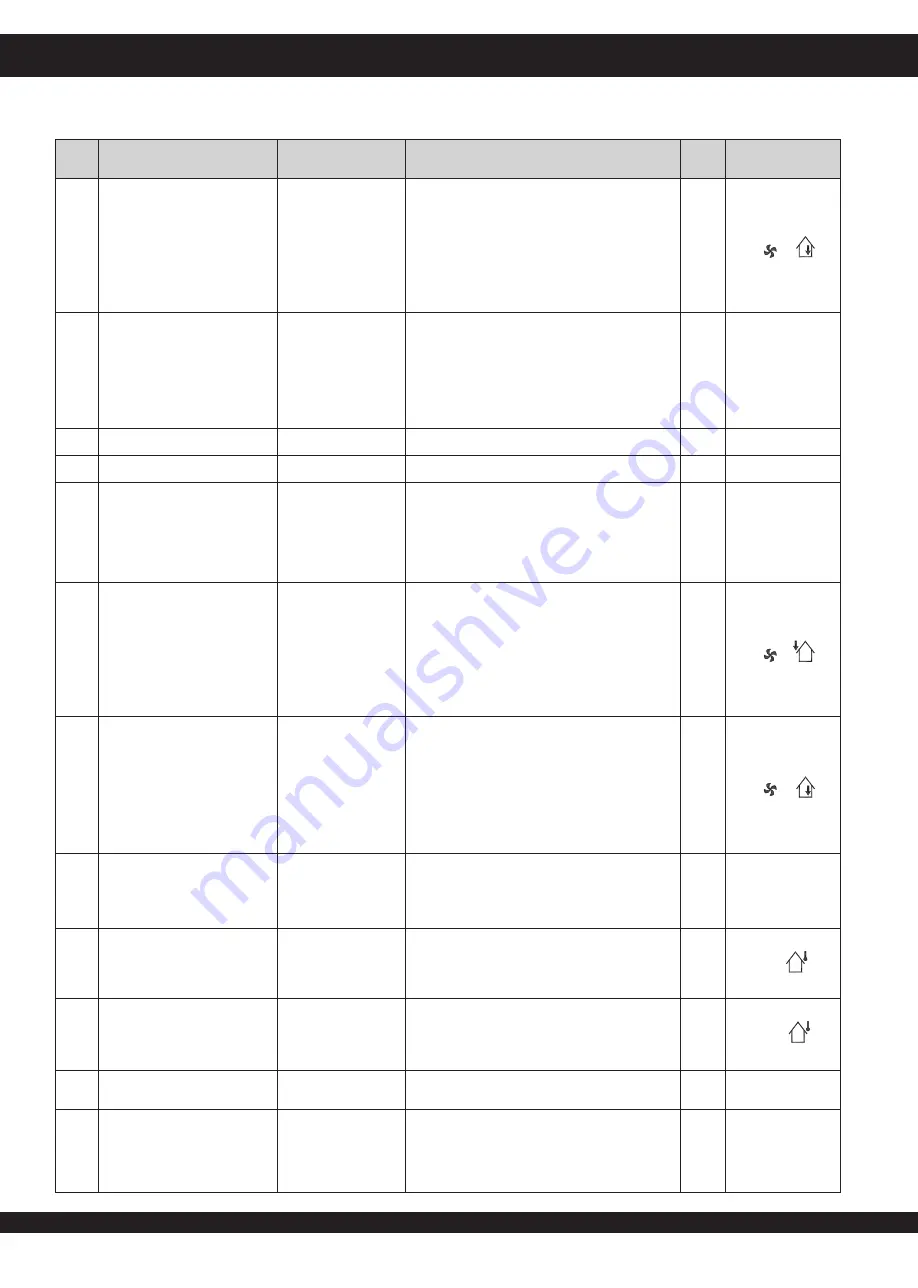
Setting values
Chapter 13
STEP
NO. DESCRIPTION
FACTORY SETTINGS
REN. EXC. “+”
ADJUSTING RANGE
STEP
DISPLAY TEXT +
SYMBOLS
20
Extract fan mode
switching input 1
5
0
(= Extract fan off)
1
(= Absolute min. flow rate 50m
3
/h)
2
(= Flow rate mode 1)
3
(= Flow rate mode 2)
4
(= Flow rate mode 3)
5
(= Multiple switch)
6
(= Maximum flow rate)
7
(= no fan activation)
CN1
21
Selection input 2
1
0 (= normally open contact)
1 (= 0 - 10V input)
2 (= normally closed contact)
3 (= input 2/
bypas open
12V;
bypass closed
0V)
4 (= input 2/
bypas open
0V;
bypass closed
12V)
V2
22
Minimum voltage input 2
0,0 V
0,0 Volt - 10,0 Volt
0,5 V
V2 MIN
23
Maximum voltage input 2
10,0 V
0,0 Volt- 10,0 Volt
0,5 V V2 MAX
24 Conditions
switching input 2
0
0
(off)
1
(on)
2
(= On if conditions bypass open satisfied)
3
(= Bypass control)
4
(= Bedroom valve)
CN2
25
Supply fan mode
switching input 2
5
0
(= Input fan off)
1
(= Absolute min. flow rate 50m
3
/h)
2
(= Flow rate mode 1)
3
(= Flow rate mode 2)
4
(= Flow rate mode 3)
5
(= Multiple switch)
6
(= Maximum flow rate)
7
(= No input fan activation)
CN2
26
Extract fan mode
switching input 2
5
0
(= Extract fan off)
1
(= Absolute min. flow rate 50m
3
/h)
2
(= Flow rate mode 1)
3
(= Flow rate mode 2)
4
(= Flow rate mode 3)
5
(= Multiple switch)
6
(= Maximum flow rate)
7
(= No extract fan activation)
CN2
27
Geo heat exchanger
OFF
OFF (= Valve control geo heat
exchanger off)
ON (= Valve control geo heat
exchanger on)
EWT
28
Minimum temperature
geo heat exchanger
(Below this temperature
the valve opens.)
5,0 °C
0,0 °C - 10,0 °C
0,5 °C
EWT T-
29
Maximum temperature
geo heat exchanger
(Above this temperature
the valve opens.)
25,0 °C
15,0 °C - 40,0 °C
0,5 °C EWT T+
30 RH-sensor
OFF
OFF
(= RH-sensor not active)
ON
(= RH-sensor active)
31 Sensitivity
RH-sensor
0
-2
most sensitive
-1
↑
0
default setting RH-sensor
+1
↓
+2
least sensitive


