•
UNDERSTANDING THE REAR PANEL
CONNECTIONS AND OPTIONS
The rear panel of the DDM354 contains the following connections
and buttons:
RESET:
Use to reset the device. Take a small object like the end of
a paper clip and insert it into the RESET opening. To power cycle
the device, hold for less than
5
seconds. To reset to factory default
settings, hold for more than
10
seconds. The DDM354 will reset
and reboot.
ETHERNET:
Use to connect to an Ethernet-enabled device such as
a computer or a wireless access point (LAN switch, router).
CABLE:
Use to connect to the coaxial cable from your Internet
service provider.
POWER:
Use to connect to the power adapter. Plug the other end
into the wall power outlet.
•
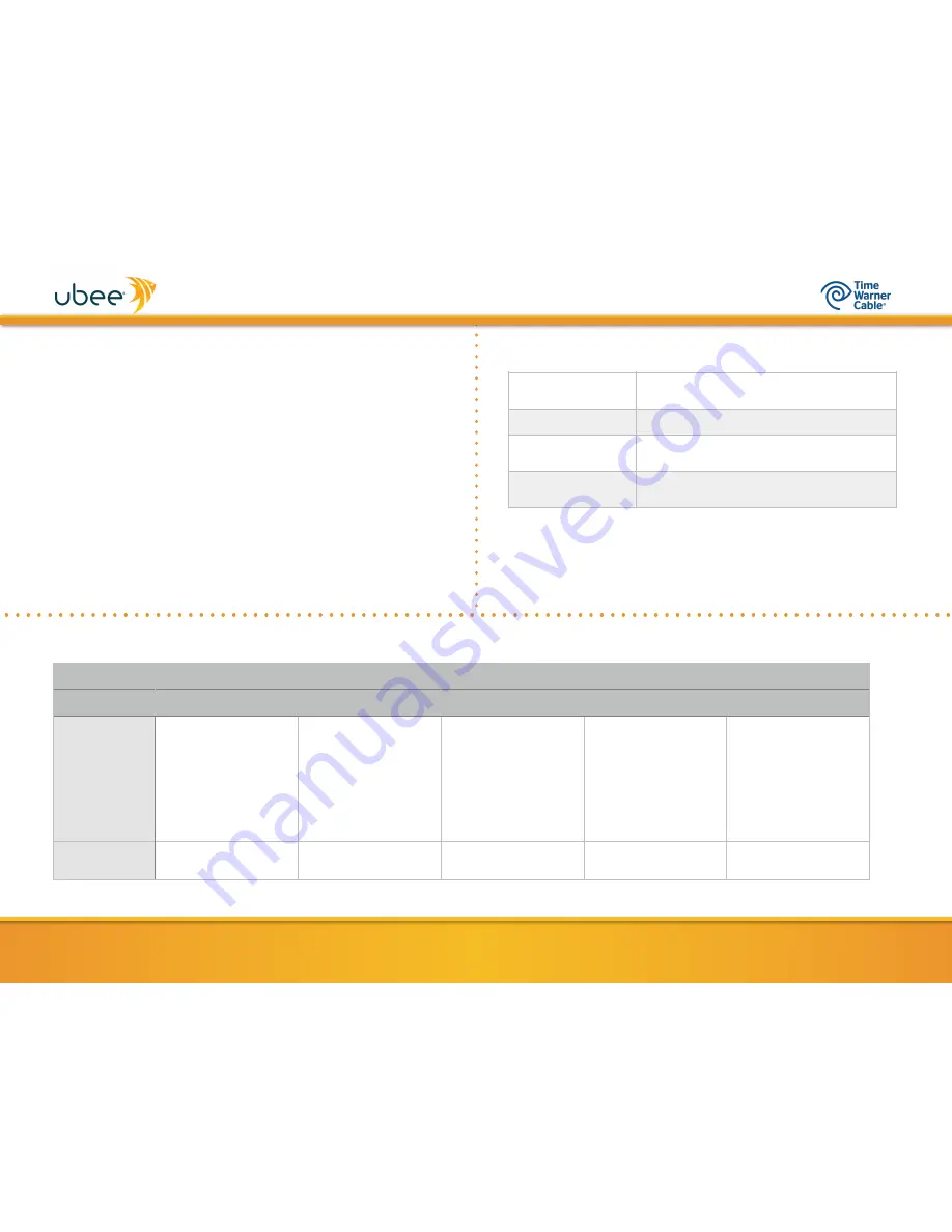
BASIC MODEM INFORMATION
www.ubeeinteractive.com
2
Example of Cable
RF MAC Address
84:4B:F5:4B:48:8C
Firmware Version
3.37.xxxx
Compatibility
DOCSIS 3.0/2.0.0/1.x
Ethernet 10/100/1000 Mbps
Local Web
UI Access
http://192.168.100.1
•
LED BEHAVIOR
LED LABEL
READY
US
DS
ETH
PWR
COLOR
Green
Green/Blue
Green/Blue
Blue/Green
Green
Cable Modem
Normal
Operation
FLASH
=
Obtaining IP/Config
ON
=
Network Connected
OFF
=
Network Connect Failed
ON
= US Lock
FLASH
=
US Scan in Progress
GREEN
=
Single Channel
BLUE
=
Bonded Channel
ON
= DS Lock
FLASH
=
DS Scan in Progress
GREEN
=
Single Channel
BLUE
=
Bonded Channel
BLUE
=
Gigabit Ethernet
Connection
GREEN
=
10/100 Ethernet
Connection
ON
=
Internal Power On
FLASH
=
Power On Failed
Firmware
Upgrade
ON
FLASH
FLASH
May
FLASH
if device is
connected
ON


