background image

Ubee Interactive

Using the WLAN Option

Ubee UBC1301-AA00 Advanced Wireless Voice Gateway Subscriber User Guide • March 2017

50

6.3.6

Deploying and Troubleshooting the Wireless Network

Use the information in this section to help you understand, deploy, and troubleshoot your 
wireless environments:



Understanding Received Signal Strength on page 50



Estimating Wireless Cable Modem to Wireless Client Distances on page 50



Understanding the 2.4GHz and 5GHz Bands on page 53



Selecting a Wireless Channel on page 53

6.3.6.1

Understanding Received Signal Strength

Received signal strength (RSSI) is measured from connected wireless client devices to 
the UBC1301-AA00. This value can significantly impact wireless speeds/performance. It is 
determined by:



Materials (for example, open air, concrete, trees)



Distance between wireless clients and the wireless cable modem



Wireless capabilities of the client devices 

6.3.6.2

Estimating Wireless Cable Modem to Wireless Client Distances

The information in this section helps you to determine how far a wireless cable modem 
can be placed from wireless client devices. Environmental variances include the 
capabilities of wireless clients and the types of material through which the wireless signal 
must pass. When the wireless cable modem and wireless clients reach the distance 
threshold between each other, network performance degrades.

To determine wireless gateway placement:

PS Pretend 
Retry Limit

Allows you to set the PS (Power Save) Pretend Retry Limit. Many times we consider that packet 
loss is due to a momentary problem that will resolve itself. PS pretend refers to the mechanism 
when we “pretend” that during a time period, the wireless station is doing power save. During this 
period, we stop sending traffic to this station and failing packets are recovered and saved to the 
power save queue. The retry limit is the number of times to do successive PS Pretend. The typically 
suggested value is around 5. In some cases, high values (10 or more) may be beneficial. A value of 
zero means the feature is disabled.

PS Pretend 
Threshold

Allows you to set the PS (Power Save) Pretend Threshold. PS pretend does not activate 
immediately on the first loss in threshold mode when a successive count of transmission failure 
reaches the threshold, then PS pretend activates. The packets prior to hitting the thresholds are 
lost. This offers a fix for dead link problems in multilink once the threshold is hit. With a value of 0 it 
is disabled. The suggested value is 5 or 10.

ACS Mode

Allows you to set the ACS (Auto Channel Selection) mode. Options are:

Œ

SCA: Stable Channel Switching

Œ

FCS: Fast Channel Switching

Apply/Save

Applies and saves changes.

Label

Description 

Summary of Contents for UBC1301-AA00

Page 1: ...oice Gateway Firmware Version 12 2 3101 20 Subscriber User Guide March 2017 www ubeeinteractive com 9155 East Nichols Avenue Suite 220 Centennial CO 80112 Sales email amsales ubeeinteractive com Suppo...

Page 2: ...y any entity either internal or external to Ubee except in accordance with applicable agreements contracts or licensing without the express written consent of Ubee and the business management owner of...

Page 3: ...Behavior 6 1 6 Specifications Standards and Firmware 7 1 7 Default Values and Logins 9 1 8 Device Label 10 2 Installing the UBC1301 AA00 12 2 1 Setting Up and Connecting the UBC1301 AA00 12 2 1 1 Wal...

Page 4: ...AN Option 34 6 1 1 Using the Setup Option 35 6 1 2 Using the Operation Mode Option 36 6 2 Using the LAN Option 37 6 2 1 Using the DHCPv4 Option 37 6 2 2 Using the DHCPv6 Option 39 6 2 3 Using the DHCP...

Page 5: ...n 74 6 6 1 Using the Account Option 74 6 6 2 Using the Backup Restore Option 75 6 6 3 Using the Factory Default Option 76 6 6 4 Using the Client List Option 77 6 7 Using the Diagnostics Option 78 6 7...

Page 6: ...LEDs on page 5 Specifications Standards and Firmware on page 7 Default Values and Logins on page 9 Device Label on page 10 1 1 Safety and Regulatory Information Use the following information to bette...

Page 7: ...1 1 2 Eco Environmental Statements The following eco environmental statements apply to the UBC1301 AA00 Packaging Collection and Recovery Requirements Countries states localities or other jurisdiction...

Page 8: ...ser Guide March 2017 3 1 2 Application Example The following diagram illustrates the general connection topology and applications of the UBC1301 AA00 1 3 Requesting Support Contact your service provid...

Page 9: ...ge 1 Power Cable Input 100 120VAC 60Hz 1 2A Max CE and UL Certified Sample image actual appearance subject to change 1 Battery NOTE The battery is not included in the product packaging by default You...

Page 10: ...bscriber User Guide March 2017 5 1 5 Device Panels Connections and LEDs 1 5 1 Device Front and Rear Panels The following images represent the UBC1301 AA00 front and rear panels Connection descriptions...

Page 11: ...its status when an Ethernet device is connected CABLE Connects to the cable outlet with the cable provided by your service provider or a cable splitter connected to the cable outlet TEL 1 TEL 2 Connec...

Page 12: ...installed Flashes When battery power level is low 30 minutes or less remaining WPS White When a user pushes the WPS button or triggers WPS via the web user interface the WPS LED flashes for 4 minutes...

Page 13: ...160 320 640 1280 2560 5120 Ksps RF cable Output Power TDMA ATDMA 8dBmV to 54dBmV 32 64 QAM ATDMA Only 8dBmV to 55dBmV 8 16 QAM 8dBmV to 58dBmV QPSK S CDMA 8dBmV to 53dBmV all modulations Actual speeds...

Page 14: ...g 2 6 lb Power 100 120Vac 60Hz 1 2A internal PSU Operating Temperature 0 C 45 C 32 F 113 F Humidity 5 90 non condensing Optional battery supports continuous voice service during power outages up to 8...

Page 15: ...ice Also called the network key or the wireless password The default WPA pre shared key is a randomly generated character string 16 characters in length and can be found on the device label Example WP...

Page 16: ...splays the URL or web address to use when accessing the Web user interface for the device GUI username Displays the user name to be entered when accessing the Web user interface for the device GUI pas...

Page 17: ...ntents from the device packaging 2 Place the UBC1301 AA00 in the best location to connect to other devices such as PCs or gaming consoles Place the UBC1301 AA00 Advanced Wireless Voice Gateway and wir...

Page 18: ...or to a cable splitter connected to the wall outlet 7 Connect an analog telephone if you will be using the device for telephone service to the TEL1 or TEL2 port on the back panel of the device Use an...

Page 19: ...ting a Telephone Line on page 15 Connecting a Wireless Device on page 15 2 2 1 Connecting an Ethernet Device You can connect up to three additional Ethernet devices to the UBC1301 AA00 To connect anot...

Page 20: ...Wireless Device Use the following steps to connect a wireless device client to the UBC1301 AA00 for example a laptop computer Default values are found in the steps below To connect a wireless device 1...

Page 21: ...45 Default Security and Encryption Methods WPA2 PSK with AES encryption 3 Confirm connectivity by opening a Web browser on the wireless client device and going to any Web site NOTE The Web interface a...

Page 22: ...network interface card Power cycle the UBC1301 AA00 by removing the power adapter from the electrical outlet and plugging it back in Wait for the device to re establish communications with your cable...

Page 23: ...User Interface on page 20 3 1 Accessing the Web User Interface Locally Access the Web user interface for the UBC1301 AA00 from a Web browser such as Internet Explorer on a Windows computer Default lo...

Page 24: ...log that appears enter the username and password and click OK Standard User Web Interface Login Username admin Password Random password of 12 alpha numeric characters can be found on the device label...

Page 25: ...Subscriber User Guide March 2017 20 3 2 Logging Out of the Web User Interface To log out of the UBC1301 AA00 web user interface click the Logout icon on the main menu After logging out you are return...

Page 26: ...Ubee Interactive Logging Out of the Web User Interface Ubee UBC1301 AA00 Advanced Wireless Voice Gateway Subscriber User Guide March 2017 21...

Page 27: ...Using the CM Info Option To access cable modem information 1 Access the Web user interface Refer to Accessing the Web User Interface Locally on page 18 2 Click Cable Modem from the top main menu 3 Cli...

Page 28: ...ion Compliant Defines the current DOCSIS standard supported by the UBC1301 AA00 Hardware Version Defines the internal version number that identifies the hardware design Software Version Defines the fi...

Page 29: ...s Voice Gateway Subscriber User Guide March 2017 24 To view connection information 1 Click CM Info from the left side menu 2 Click Connection under CM Info Please note that the following screen exampl...

Page 30: ...atus and file name of the configuration file currently used by the UBC1303 AA00 Security Displays the status of the security settings enabled disabled CM Downstream Channel Info Channel Numbers the do...

Page 31: ...Uncorrectables Displays the quantity of codewords which are not correctable CM Upstream Channel Info Channel Numbers the upstream channels Lock Status Displays if the device has locked successfully to...

Page 32: ...o Option Ubee UBC1301 AA00 Advanced Wireless Voice Gateway Subscriber User Guide March 2017 27 Label Description Time Displays the date and time of the event Priority Displays the priority of the even...

Page 33: ...ccess telephony information 1 Click Telephony from the top main menu 2 Click MTA from the left side menu The following sub menus are available Using the Status Option on page 28 Using the DHCP Option...

Page 34: ...portion of the device Telephony Security Displays the security mode of the MTA Basic Hybrid or Security Telephony TFTP Displays if the MTAs TFTP server is available Telephony Call Server Registration...

Page 35: ...Primary DNS Displays the main domain name server Secondary DNS Displays the secondary domain name server Lease Timers Lease Time Remaining Displays the time left on the DHCP lease Rebind Time Remaini...

Page 36: ...low the screen example Label Description Error Codewords Unerrored Codewords Displays the number of codewords passed without error Correctable Codewords Displays the number of codewords corrected Unco...

Page 37: ...onfiguration file and enterprise MIB settings To view telephony provisioning details 1 Click MTA from the left side menu 2 Click Provisioning funder MTA Field descriptions are listed below the screen...

Page 38: ...re listed below the screen example Label Description MTA Config File Filename Displays the config file being used Contents Displays the current settings Enterprise MIBs OID Displays the eMTA MIBs Valu...

Page 39: ...on page 41 Using the Advanced Settings Options on page 54 Using the Parental Control Option on page 71 Using the Management Option on page 74 Using the Diagnostics Option on page 78 To access the gat...

Page 40: ...ace Internet IP Subnet Mask Displays the IP subnet mask for the Internet interface IPv6 Address Displays the current WAN public IPv6 address obtained from the service provider IPv4 Address Displays th...

Page 41: ...mode To configure the router operation mode 1 Click WAN from the left side menu 2 Click Operation Mode under WAN Field descriptions are listed below the screen example IPv4 DNS Servers Lists the IPv4...

Page 42: ...cts the entire device meaning all networks become bridged Only the Status and Wireless menus are visible when in Bridge mode Note If you place a device in Bridge mode and only one public IP address ha...

Page 43: ...ies and learn about other devices on the network In turn a device can leave a network smoothly and automatically when it is no longer in use Gaming consoles and Wen cameras are examples of devices tha...

Page 44: ...indows 7 devices that turn off the network interface when they go into standby mode This results in slow Web browsing until the device gets a new IP address via DHCP Add Entries Click the Add Entries...

Page 45: ...DHCPv6 Server Enables the Ethernet Switch LAN Interface and Prefix Start interface ID Allows you to enter the start Interface ID Start interface ID Allows you to enter the end Interface ID Leased Time...

Page 46: ...and configure wireless information Enable Rapid Commit Enables Rapid Commit When enabled the server recognizes this option in Solicit messages sent from the DHCPv6 client The server and client then us...

Page 47: ...e 46 Using the WMM Option on page 48 6 3 1 Using the Basic Option The WLAN Basic option allows you to configure basic settings for both the 2 4GHz and 5GHz radio bands including channel number and ban...

Page 48: ...tworking standard Available modes for selection are 2 4GHz B G N mix default G N mix B G mix and N only 5GHz A N AC mix default N AC mix AC only A only N only WMM Support When WMM WiFi Multimedia supp...

Page 49: ...5GHz radio bands To configure wireless security 1 Click WLAN from the left side menu 2 Click Security under WLAN Field descriptions follow the screen example Sideband for Control Channel Only when us...

Page 50: ...ES Auto NOTE AES is the most secure and efficient You should only enable TKIP if you have a very old device that cannot support AES TKIP will also compromise the security of your device and will resul...

Page 51: ...available for configuring the 2 4GHz and 5GHz radios WPS Enable Check ON or OFF to enable or disable the WPS option WPS Mode Allows you to choose between the 2 WPS modes 1 PIN User must enter the clie...

Page 52: ...ient to connect to this device However if you use other security mechanisms for access to the wireless network clients must still adhere to those restrictions Allow creates a list of wireless clients...

Page 53: ...from the left side menu 2 Click WMM under WLAN Descriptions follow the screen sample below MAC filter based Probe Response Allows you to turn probe responses Off or On Probe responses are sent to wir...

Page 54: ...ness Airtime Fairness gives equal amounts of air time instead of equal number of frames to each wireless client regardless of its theoretical data rate This will ensure higher download speed to faster...

Page 55: ...When the wireless cable modem and wireless clients reach the distance threshold between each other network performance degrades To determine wireless gateway placement PS Pretend Retry Limit Allows yo...

Page 56: ...ransmit Power use 30dBm Receiver Sensitivity use RSSI value Allowable Free Space Loss Allowable Free Space Loss Materials Attenuation Value Optimal Distance in Feet Between the UBC1301 AA00 and a Wire...

Page 57: ...for both a Windows and Mac computer in the table below If the wireless computer is not connected refer to Connecting a Wireless Device on page 15 Checking Wireless Signal Strength and Speed Windows P...

Page 58: ...e control over only one wireless device in an environment where there may be several you can change the wireless channel on your device to one that is not heavily used NOTE To change the wireless broa...

Page 59: ...following table shows the 5GHz channel list and the corresponding frequencies 6 4 Using the Advanced Settings Options Advanced options provide many settings to configure your UBC1301 AA00 To view Adv...

Page 60: ...Using the DMZ Option on page 67 Using the DDNS Option on page 68 Using the DNS Override Option on page 69 Using the NTP Option on page 70 6 4 1 Using the Options option The Options screen allows you...

Page 61: ...sted VoIP services prefer this function to be performed by their own session border controller SBC and require the SIP to be disabled Some IP PBXs may require SIP enabled RTSP Real time streaming prot...

Page 62: ...the Allowed Services section IPv6 Firewall Protection Defines the level of IPv6 protection Choices are On and Off Services are based on the protection level and are displayed in the Allowed Services s...

Page 63: ...ow the screen example 6 4 4 Using the MAC PassThrough Option Use the MAC PassThrough option to configure a pass through table Devices in the pass through table are treated as bridge devices storing an...

Page 64: ...establishes a list and any host on this list is not able to access the network through the UBC1301 AA00 Label Description Add Click the Add button to add MAC Addresses to the pass through table The po...

Page 65: ...nced Settings from the left side menu 2 Click MAC Filter under Advanced Settings Field descriptions are listed below the screen example Label Description Add Click the Add button to add MAC Addresses...

Page 66: ...Games applications Home Security Systems Security systems that use the Internet Audio Servers VoIP Audio and VoIP applications and services See the following topics Before Setting Up Forwarding on pag...

Page 67: ...nformation to set up port forwarding IP address of each local host system for example Xbox for which you need to setup a port forwarding rule Port numbers the local host s application listens to for i...

Page 68: ...cated in your LAN Local End Point Defines the ending port number listened to by the server host located in your LAN External Start Port Defines the port number to start the range of ports to publish t...

Page 69: ...ing the Port Trigger Option Port Triggers define dynamic triggers for specific devices on the LAN This allows special applications that require specific port numbers with bi directional traffic to fun...

Page 70: ...esponses to these ports For example 1 John requests a file from the RealAudio server port 7070 Port 7070 is a trigger port and causes the device to record John s computer IP address The UBC1301 AA00 a...

Page 71: ...er Start Port Defines a port number or the starting port number in a range of port numbers Trigger End Port Defines a port number or the ending port number in a range of port numbers Target Start Port...

Page 72: ...ernet port on the UBC1301 AA00 Make sure both devices are powered on and functioning 2 Connect a Home Gateway or other device you wish to be in the DMZ to an Ethernet port on the UBC1301 AA00 3 Log in...

Page 73: ...her hosts on the Internet even if its IP address changes The DDNS service for the UBC1301 AA00 is provided through third parties and can be purchased from Dynamic Network Services Inc at www dynDNS co...

Page 74: ...lick Advanced Settings from the left side menu 2 Click DNS Override under Advanced Settings Field descriptions are listed below the screen example Label Description D DNS provider Enables selection of...
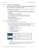
Page 75: ...NTP SNTP is a protocol for synchronizing the clocks of computing devices over networks To synchronize with Internet Time 1 Click Advanced Settings from the left side menu 2 Click NTP under Advanced Se...

Page 76: ...ft side menu 3 The following sub menu is available for selection Label Description Automatically synchronize with Internet time servers Check the box to automatically synchronize with Internet time se...
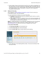
Page 77: ...ime of Day Filter option to configure time based access policies to block or allow access to specific Internet sites To set up Time of Day Filters 1 Click Parental Control from the left side menu 2 Cl...

Page 78: ...r keyword to be blocked Protocol Select the protocol type Options are UDP TCP or Both Start Port Enter the starting port number to be blocked or allowed End Port Enter the ending port number to be blo...

Page 79: ...election Using the Account Option on page 74 Using the Backup Restore Option on page 75 Using the Factory Default Option on page 76 Using the Client List Option on page 77 6 6 1 Using the Account Opti...

Page 80: ...ion To back up or restore the gateway configuration 1 Click Management from the left side menu 2 Click Backup Restore under Management 6 6 2 1 Backing Up the Current Configuration To backup and save t...

Page 81: ...e button Click the Restore button Your device will then reboot You are then presented with the login screen Enter the Username and Password to return to the User Interface Refer to Accessing the Web U...

Page 82: ...the UBC1301 AA00 To view connected devices 1 Click Management from the left side menu 2 Click Client List under Management Field descriptions follow the screen example Label Description Restore User D...
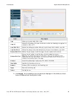
Page 83: ...by sending a test message to a specific device You can also confirm the size of data sent is the same as the size of data received 1 Choose Ping from the drop down menu 2 Enter a target IP address or...

Page 84: ...or accept the default values Label Description Utility Provides a drop down menu to choose Ping or Traceroute Ping Test Parameters Target Enter the IP address or URL name to which you want to send a...
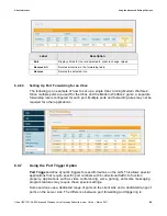
Page 85: ...Defines the specific IP address or domain for example google com to which you want to trace a route Max Hops Defines the maximum number of hops Hops are the number of routers the traceroute traverses...

Page 86: ...et and the wireless interfaces The nodes are annotated by the last 6 characters of the interface with which they are connected to the access point the UBC1301 AA00 The nodes in RED indicate the WiFi a...

Page 87: ...ubnet as the Ethernet ports and Wireless Primary Networks IMPORTANT NOTE Always consult your Cable Service Provider before enabling MoCA to be sure that the Point Of Entry Filter is properly installed...

Page 88: ...UBC1301 AA00 Gateway IP address accessed via the MoCA interface Security Mode Enabled means MoCA traffic is encrypted Disabled means MoCA traffic is not encrypted Auto Scan If true the UBC1301 AA00 a...

Page 89: ...to 8 hours of standby time Five 5 hours of talk time with 1 line active One upstream and 1 downstream channel NOTE Actual battery performance is affected by battery age and operating environment Topi...

Page 90: ...ttery Charge Module Software Driver Displays the driver used in the software Built Indicates the date and time the battery was manufactured Battery Status Current Power Source Displays the current pow...

Page 91: ...ow the screen example 8 3 Using the Interface Delay Option The Interface Delay option displays the length of time each interface will be active before being turned off when the device is operating on...

Page 92: ...xample Label Description Interface DOCSIS CM Displays the length of time in seconds the DOCSIS CM interface will be active before being turned off when the device is operating on battery power Etherne...
Page 93: ...hey are one channel CMTS Cable Modem Termination System Typically located in the cable company s headend the CMTS is equipment that provides high speed data services to subscribers such as cable Inter...

Page 94: ...ice that locates and translates domain names into IP addresses Because domain names are alphabetic they are easier to remember However the Internet is based on IP addresses Every time you use a domain...

Page 95: ...st widely installed level of the IP today an IP address is a 32 bit binary digit number that identifies each sender or receiver of information that is sent in packet form across the Internet When you...

Page 96: ...ddress Translation A technique by which several hosts or computers share a single IP address for access to the Internet NAT enables a LAN to use one set of IP addresses for internal traffic and a seco...

Page 97: ...ise SNTP Simple Network Time Protocol A protocol for synthesizing the clocks of computing devices over networks STBC Space Time Block Code A technique used in wireless communications to transmit multi...

Page 98: ...ot files TPC Transmit Power Control Sometimes called Dynamic Power Control DPC TPC is a mechanism used in radio communications to reduce the power of a radio transmitter to the minimum necessary to ma...

Page 99: ...arch 2017 94 XML Extensible Markup Language A markup language that defines a set of rules for encoding documents in a format that is both human readable and machine readable XPress XPress is a standar...

Reviews: