© 2022 Ubicquia, Inc.
4
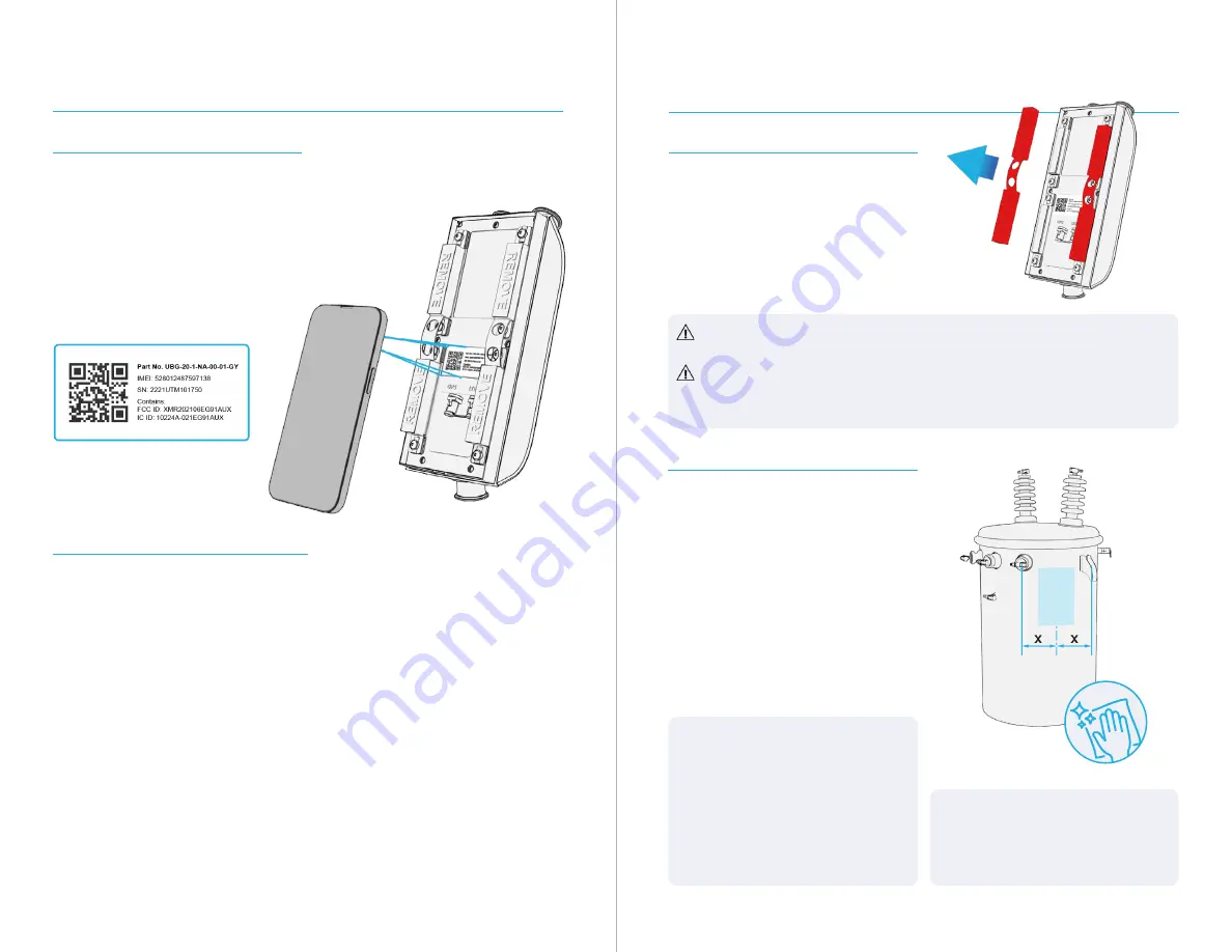
A. Scan DTM+ QR Code
Escanee el código QR de DTM+
1
EN:
Remove the UbiGrid™ DTM+
sensor unit from the box and scan the
QR code on the unit using the UbiGrid
DTM+ installation app.
ES: Retire el DTM+ de la caja y escanee
el código QR de la unidad con la app de
instalación UbiGrid™ DTM+.
2
EN:
Identify the type and kVA rating of
the transformer on which you will be
installing the DTM+ and document it in
the installation app.
ES: Identifique el tipo y la capacidad en
kVA del transformador en el que instalará
el DTM+ y ingréselos en la app de
instalación.
EN:
NOTE:
Clean the mounting
area with a dry cloth.
ES: NOTA: Limpie el área de
montaje con un trapo seco.
2
EN:
Before attaching the DTM+ sensor
unit, identify the mounting location.
The DTM+ should be mounted halfway
between the secondaries and the lifting
lug on the side closest to the pressure
relief valve, near the top of the tank.
ES: Antes de fijar el DTM+, identifique el
área de colocación. El DTM+ colocarse
a media distancia entre los secundarios
y el asa de izaje en el lado más cercano a
la válvula de alivio de presión, cerca de la
parte superior del tanque.
B. Attach the DTM+ Sensor Unit
Colocar el sensor DTM+
1
EN:
Remove the two red magnet
covers from the back of the DTM+.
ES: Retire las dos cubiertas rojas de los
imanes de la parte posterior del DTM+.
EN:
CAUTION:
Be sure to keep the DTM+ away from any metallic
surfaces or objects once the magnet covers are removed.
ES: PRECAUCIÓN: Asegúrese de mantener el DTM+ alejado de cualquier
superficie u objeto metálico una vez que se retiren las cubiertas de los
imanes.
EN:
NOTE:
If there is no pressure
relief valve, place the DTM+ on the
side opposite from the H1 primary
bushing.
ES: NOTA: Si no hay válvula de alivio
de presión, colocar la unidad de
procesamiento del DTM+ en el lado
opuesto de la boquilla primaria H1.


