34
Chapter 6: Network Tab
airFiber AF-24/AF-24HD User Guide
Ubiquiti Networks, Inc.
-
Netmask
When the netmask is expanded into its
binary form, it provides a mapping to define which
portions of the IP address range are used for the
network devices and which portions are used for host
devices. The netmask defines the address space of the
airFiber AF-24’s network segment. The 255.255.255.0
(or “/24”) netmask is commonly used on many Class C
IP networks.
-
Gateway IP
Typically, this is the IP address of the host
router, which provides the point of connection to the
internet. This can be a DSL modem, cable modem, or
WISP gateway router. The airFiber AF-24 directs data
packets to the gateway if the destination host is not
within the local network.
-
Primary DNS IP
Specify the IP address of the primary
DNS (Domain Name System) server.
-
Secondary DNS IP
Specify the IP address of the
secondary DNS server. This entry is optional and used
only if the primary DNS server is not responding.
Management VLAN
If enabled, automatically creates a
management Virtual Local Area Network (VLAN).
•
VLAN ID
(Available if
Management VLAN
is enabled.)
Enter a unique VLAN ID from 2 to 4094.
Auto IP Aliasing
If enabled, automatically generates an
IP address for the corresponding WLAN/LAN interface.
The generated IP address is a unique Class B IP address
from the 169.254.X.Y range (netmask 255.255.0.0), which
is intended for use within the same network segment
only. The Auto IP always starts with 169.254.X.Y, with X
and Y as the last two octets from the MAC address of
the airFiber AF-24. For example, if the MAC address is
00:15:6D:A3:04:FB, then the generated unique Auto IP will
be 169.254.4.251. (The hexadecimal value,
FB
, converts to
the decimal value,
251
.)
The Auto IP Aliasing setting can be useful because you
can still access and manage devices even if you lose,
misconfigure, or forget their IP addresses. Because an
Auto IP address is based on the last two octets of the MAC
address, you can determine the IP address of a device if
you know its MAC address.
airView Port
The port number associated with the
airView spectrum analyzer tool. The default value is
18888
.
For detailed information on the airView tool, refer to
“airView” on page 47
.
Mgmt Speed
This is the speed of the
Management
port. By default, the option is
Auto. The airFiber X radio
automatically negotiates transmission parameters, such as
speed and duplex, with its counterpart. In this process, the
networked devices first share their capabilities and then
choose the fastest transmission mode they both support.
To manually specify the maximum transmission link
speed and duplex mode, select one of the following
options:
100 Mbps-Full
,
100 Mbps-Half
,
10 Mbps-Full
,
or
10 Mbps-Half.
If you are running extra long Ethernet
cables, a link speed of
10 Mbps could help to achieve
better stability.
Full-duplex mode allows communication in both
directions simultaneously. Half-duplex mode allows
communication in one direction at a time, alternating
between transmission and reception.
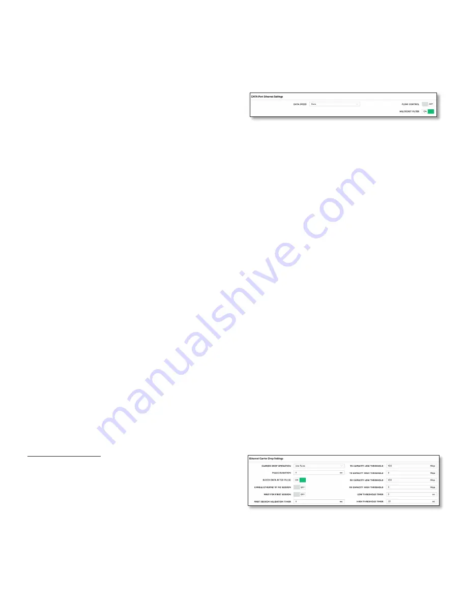
Data Port Ethernet Settings
Data Speed
This is the speed of the
Data
port.
The default is Auto
, which
allows the radio to operate at a
speed of 1 Gbps.
The AF-24 radio automatically negotiates
transmission parameters, such as speed and duplex, with
its counterpart. In this process, the networked devices
first share their capabilities and then choose the fastest
transmission mode they both support.
To manually specify the maximum transmission link
speed and duplex mode, select one of the following
options:
100 Mbps-Full
,
100 Mbps-Half
,
10 Mbps-Full
, or
10 Mbps-Half
.
Full-duplex mode allows communication in both
directions simultaneously. Half-duplex mode allows
communication in one direction at a time, alternating
between transmission and reception.
Flow Control
If enabled, the AF-24 radio generates and
responds to Ethernet layer PAUSE frames. The AF-24 radio
regulates inbound traffic from the customer’s network to
avoid buffer overflows within the AF-24 radio. Flow control
has the effect of controlling the inter-packet spacing of
packets headed into the airFiber Data interface.
Multicast Filter
If enabled, the filter blocks multicast
traffic from overloading the CPU when in-band
management is enabled. This allows the AF-24 radio to
be managed in-band when the customer’s network is
carrying large volumes of multicast traffic, such as IPTV.
The filter does not block multicast traffic going over the
radio; it simply blocks it from reaching the AF-24 radio’s
management interface CPU.
Ethernet Carrier Drop Settings
The
Ethernet Carrrier Drop
settings are used to control
failover switching between the primary and backup link in
response to capacity loss due to rain.
Carrier Drop Operation
This setting is used to control
the
Ethernet Carrier Drop
feature. Settings are:
Disabled
,
Enabled
, and
Use Pulse
. The default is
Disabled
.
Use Pulse
and
Enabled
are the two different methods used
to signal to the failover mechanism that it should switch to
the backup link:
Summary of Contents for airFiber 24
Page 1: ...24 GHz Point to Point Radio Models AF 24 AF 24HD ...
Page 2: ......
Page 24: ...20 Chapter 2 Installation airFiber AF 24 AF 24HD User Guide Ubiquiti Networks Inc ...
Page 28: ...24 airFiber AF 24 AF 24HD User Guide Ubiquiti Networks Inc ...
Page 32: ...28 Chapter 4 Dashboard airFiber AF 24 AF 24HD User Guide Ubiquiti Networks Inc ...
Page 36: ...32 Chapter 5 Wireless Tab airFiber AF 24 AF 24HD User Guide Ubiquiti Networks Inc ...
Page 40: ...36 airFiber AF 24 AF 24HD User Guide Ubiquiti Networks Inc ...
Page 44: ...40 Chapter 7 Services Tab airFiber AF 24 AF 24HD User Guide Ubiquiti Networks Inc ...
Page 48: ...44 Chapter 8 System Tab airFiber AF 24 AF 24HD User Guide Ubiquiti Networks Inc ...
Page 54: ...50 Chapter 9 Tools airFiber AF 24 AF 24HD User Guide Ubiquiti Networks Inc ...
Page 60: ...56 Appendix B Safety Notices airFiber AF 24 AF 24HD User Guide Ubiquiti Networks Inc ...
Page 68: ...w w w u b n t c o m ...


