background image

28/09/2020

AF-11 Quick Start Guide

https://dl.ubnt.com/qsg/AF-11/AF-11_EN.html

4/15

Link LED

MIMO LED

MGMT LED

LED remains lit to indicate the boot sequence is underway.

Initializing airFiber Software 

When the airFiber application begins to boot under

airOS®, the Signal 4 LED goes from solidly on to a 2.5 Hz  ash. This continues until the

AF‐11FX is fully booted.

Signal Level 

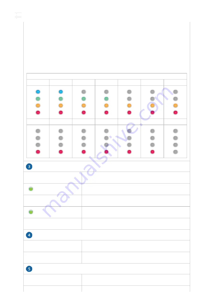
Once fully booted, the Signal 1-4 LEDs act as a bar graph showing how

close the AF‐11FX is to ideal aiming. This is auto-scaled based on the link range, the

antenna gains, and the con gured TX power of the remote AF‐11FX. Each Signal LED

has three possible states: On, Flashing, and Off. All Signal LEDs would be solidly on in an

ideal link. For example, if the link has a 1 dB loss, the Signal 4 LED will  ash; a 2 dB loss

and the Signal 4 LED will turn off. The full bar graph LED states are shown below.

dB loss

0

-1

-2

-3

-4

-5

-6

-7

-8

-9

-10

-11

-12

-13

Off

RF Off

Syncing

Beaconing

Registering

On

Operational

Off

Radio Con gured in SISO Mode

On

Radio Con gured in MIMO Mode

Off

No Ethernet Link

AF-11 Quick Start Guide

Summary of Contents for airFiber AF-11

Page 1: ... your application Installation Requirements Clear line of sight between airFiber radios Vertical mounting orientation Mounting point At least 1 m below the highest point on the structure For tower installations at least 3 m below the top of the tower Ground wires min 10 AWG 5 mm and max length 1 m As a safety precaution ground the airFiber radio to grounded masts poles towers or grounding bars WAR...

Page 2: ...ed for proper operation SISO mode One Duplexer of either band type MIMO mode Two Duplexers of the same band type Optional If not using PoE DC power source and 12 30 AWG power cable Outdoor shielded Category 6 or above cabling and shielded RJ 45 connectors are required for all wired Ethernet connections Hardware Overview Note Duplexers must be purchased separately The Duplexer s must match the term...

Page 3: ...ed here allowing connection to an RF cable Chain 1 is covered by the removable duplexer cap Signal 4 LED will light blue when on Signal 3 LED will light green when on Signal 2 LED will light yellow when on Signal 1 LED will light red when on Bootup to airOS When powering on the Power MIMO LINK and Signal 1 4 LEDs light on Once the CPU code takes over the MIMO LINK and Signal 1 3 LEDs turn off Signa...

Page 4: ...owing how close the AF 11FX is to ideal aiming This is auto scaled based on the link range the antenna gains and the con gured TX power of the remote AF 11FX Each Signal LED has three possible states On Flashing and Off All Signal LEDs would be solidly on in an ideal link For example if the link has a 1 dB loss the Signal 4 LED will ash a 2 dB loss and the Signal 4 LED will turn off The full bar gra...

Page 5: ...e When In Band Management is disabled the MGMT port is the only port that can monitor con gure and or update rmware To reset to factory defaults press and hold the Reset button for more than 10 seconds while the device is already powered on Gigabit PoE port for handling all user traffic and powering the device The terminal block can be used to power the AF 11 with 50VDC 1 2A instead of PoE The TX an...

Page 6: ...1 Install a ground wire and mount the AF 11 on the airFiber AF 11G35 antenna or a compatible antenna At the installation site install the antenna with the mounted AF 11 radio see the antenna s Quick Start Guide for installation instructions Connect the DATA port to your LAN and connect power PoE or DC power to the AF 11 Establish and optimize the RF link Installing the Duplexers Installing the Dup...

Page 7: ...ge to the Duplexer 4 5 6 Repeat steps 1 5 for the other radio to be used in the link ensuring that the numbers on the second radio s Duplexers are in the reverse order of the numbers on the rst radio s Duplexers Note For example if the numbers on the rst radio s Duplexers are left to right 2 4 and 4 2 the numbers on the second radio s Duplexers should be 4 2 and 2 4 Connecting Power over Ethernet ...

Page 8: ...curity a Select the Key Type HEX or ASCII b For the Key eld HEX Enter 16 bytes eight 16 bit hexadecimal digits 0 9 A F or a f You can omit zeroes and use colons similar to the IPv6 format ASCII Enter a combination of alphanumeric characters 0 9 A Z or a z 9 Click Save Changes 10 In Band Management is enabled by default so each airFiber radio must have a unique IP Address If the airFiber radios use...

Page 9: ...ould be as short as possible and no longer than one meter in length Mount to the airFiber AF 11G35 Antenna 1 Attach an RF Cable to an RF connector labeled H or V Then slide the silicone boot over the RF connector to protect it If using MIMO mode remove the cap over the second RF connector V or H and attach an RF Cable Then slide the silicone boot over the RF connector to protect it 2 3 4 Note Alig...

Page 10: ...ssors such as the Ubiquiti Ethernet Surge Protector model ETH SP G2 at the end of each link Install the rst surge protector within one meter of the airFiber DATA port and install the second surge protector at the ingress point of the location housing the wired network equipment Alignment Tips To accurately align the airFiber radios for best performance you MUST align only one end of the link at a ...

Page 11: ...ngest signal level on the Master Note Refer to the Signal LEDs section for details on the signal values Note Maximum signal strength can best be achieved by iteratively sweeping through both azimuth and elevation 5 Master Aim the Master at the Slave to achieve the strongest signal level on the Slave 6 Repeat steps 4 and 5 until you achieve an optimal link with all four Signal LEDs solidly lit This...

Page 12: ... Ethernet DC Power Block Supported Voltage Range 38 56VDC Certi cations FCC Part 101 ETSI EN 302 217 Mounting AF 11G35 Mount Compatible Operating Temperature 40 to 55 C 40 to 131 F Networking Interface Data 1 10 100 1000 Ethernet Port Management 1 10 100 Ethernet Port System Processor INVICTUS 2 IC Maximum Throughput 1 2 Gbps Encryption 128 bit AES OS airOS F Wireless Modes SISO MIMO Radio Operati...

Page 13: ... the power cord with one that is not the provided approved type Never use an adapter plug to connect to a 2 wire outlet as this will defeat the continuity of the grounding wire b The equipment requires the use of the ground wire as a part of the safety certi cation modi cation or misuse can provide a shock hazard that can result in serious injury or death c Contact a quali ed electrician or the ma...

Page 14: ...adiator and your body This transmitter must not be co located or operating in conjunction with any other antenna or transmitter AVIS IMPORTANT Déclaration sur l exposition aux rayonnements Cet équipement est conforme aux limites prévues pour l exposition aux rayonnements dans un environnement non contrôlé Lors de l installation et de la mise en fonctionnement de l équipement assurez vous qu il y a...

Page 15: ...at are applicable to it Country List AT BE BG CY CZ DE DK EE EL ES FI FR HR HU IE IT LV LT LU MT NL PL PT RO SE SI SK UK BFWA Broadband Fixed Wireless Access members noted in blue Note This device meets Max TX power limit per ETSI regulations WEEE Compliance Statement Declaration of Conformity Online Resources 2020 Ubiquiti Inc All rights reserved AF 11 Quick Start Guide ...

Reviews: