background image

Activating an Integrated Tool Tag

Activating an Integrated Tool Tag

The Integrated Tool Tag includes a battery. To reduce the loss of battery life, the tag is supplied in

the deep sleep (deactivated state).

To activate the tag:

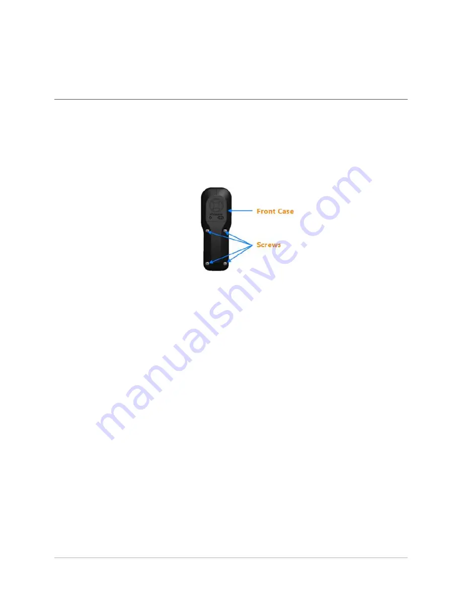
1. Separate the body of the tag from the front cover by unscrewing the four screws on the

front case of the tag, shown in the following figure.

Front Case of the Integrated Tool Tag

2. Connect the Head Unit of the tag to the twenty-way pin connector on the printed circuit

board of the tag, as shown in the following figure.

10

Summary of Contents for Dimension4 UWB+BLE Tag

Page 1: ...bisense DIMENSION4 Tool Tag User Guide Tuesday July 26 2022 Ubisense Limited St Andrew s House St Andrew s Road Cambridge CB4 1DL United Kingdom Telephone 44 0 1223 535170 Website http www ubisense ne...

Page 2: ...is provided in connection with Ubisense products No license express or implied to any intellectual property rights is granted by this document Ubisense encourages all users of its products to procure...

Page 3: ...Tag 5 Activating an Integrated Tool Tag 10 Checking that a Tool Tag is Activated 11 Putting a Tool Tag into Deep Sleep 12 Replacing the Battery of a Tool Tag 13 Disposing of Batteries 14 Resetting the...

Page 4: ...you can locate the tool to an accuracy of 15 cm in 3D in real time You can use Tool Tags in different types of environments including industrial sites Types of Tool Tags Ubisense provides the followi...

Page 5: ...Feature Description A Power LED yellow Indicates that the tag is receiving power and is communicating with the DIMENSION4 Real time Location System B Programmable LEDs green and red By default these L...

Page 6: ...ower Cord Connector The Battery Unit and Integrated Tool Tag have a mini USB power cord connector on the top This cord connector is used for transferring power to the Head Unit E Philips Head Screws S...

Page 7: ...a screw terminal block Cut the cable to the required length and prepare the wire ends as described in Preparing a Head and Battery Unit Tool Tag Connect the wire ends into the screw terminal block Yo...

Page 8: ...Before you attach a Head and Battery Unit Tool Tag to a tool you must cut the wire to the correct length depending on your particular requirements To prepare the tag cut the wire to the appropriate le...

Page 9: ...d Length 2 Strip the wires and twist the individual strands together as shown in the following figures Stripping the Wires Prepared Wires 3 Remove the battery holder PCBA from the Battery Unit Remove...

Page 10: ...ery and Holder Battery Unit without the Battery 4 Pass the wire through the wire entry slot as shown in the following figure Passing the Wire through the Wire entry Slot 5 Connect the wires to the ter...

Page 11: ...terminal is marked on the Printed Circuit Board with a symbol The wire with the White Stripe is the positive wire 6 Install the strain relief cable tie on the cable as shown in the following figure In...

Page 12: ...ry Holder Installed in the Box 8 Reinstall the battery and assemble the Battery Unit as shown in the following figure Assembled Head and Battery Unit The yellow LED on the Head Unit slowly increase in...

Page 13: ...deep sleep deactivated state To activate the tag 1 Separate the body of the tag from the front cover by unscrewing the four screws on the front case of the tag shown in the following figure Front Cas...

Page 14: ...MENSION4 Real time Location System 3 Replace the front case of the tag by connecting the four screws Checking that a Tool Tag is Activated To check that a Tool Tag has been activated insert a paper cl...

Page 15: ...e It then starts blinking again a Count the number of times the LED blinks brightly This can be from one to five blinks b Using the paper clip or screwdriver press the button on the tag the same numbe...

Page 16: ...one of the following l Battery Unit Remove the old battery and then insert a new battery l Integrated Tool Tag Remove the old battery by unplugging the battery connector Insert a new battery and then...

Page 17: ...atteries Disposing of Batteries After you have replaced batteries dispose of the old batteries according to the manufacturer s instructions available at http www tadiranbat com index php shipping and...

Page 18: ...nse for the SmartSpaceVisibility feature on the Tags page of SmartSpace Web See Resetting Battery Status on the SmartSpace website l By using the command line tool ubisense_tag_battery_replaced and sp...

Page 19: ...a residential installation This equipment generates uses and can radiate radio frequency energy and if not installed and used in accordance with the instructions may cause harmful interference to radi...

Page 20: ...s fonctionnement du dispositif This Class B digital apparatus complies with Canadian CAN ICES 3 B NMB 3 B Cet appareil num rique de la classe B respecte toutes les exigences du R glement sur le mat ri...

Reviews: