Ubisense
– Ultra-wideband Location System – UBISENSOR30V1 Revision D
Introduction
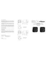
The UBISENSOR30V1 is a basestation used by the Ubisense Location System, which
supports the real-time location of objects. It detects ultra-wideband (UWB) pulses emitted by
wireless tags (Ubitags), allowing the 3D position of the tags to be found. The use of UWB
technology enables greater positioning accuracy than other wireless technologies, because it
is much less susceptible to multipath interference effects. Applications of the system include
healthcare, workplace productivity, security, retail management and manufacturing.
This document describes the features and specifications of the UBISENSOR30V1, important
regulatory information concerning its use, and details on how to diagnose potential problems.
Regulatory Information for the United States of
America
The UBISENSOR30V1 is approved under Part 15.249 of the FCC rules:
This device complies with Part 15 of the FCC Rules. Operation is subject to the following
two conditions: (1) this device may not cause harmful interference, and (2) this device
must accept any interference received, including interference that may cause undesired
operation.
N
OTE
: This equipment has been tested and found to comply with the limits for a Class B
digital device, pursuant to part 15 of the FCC Rules. These limits are designed to provide
reasonable protection against harmful interference in a residential installation. This
equipment generates, uses and can radiate radio frequency energy and, if not installed
and used in accordance with the instructions, may cause harmful interference to radio
communications. However, there is no guarantee that interference will not occur in a
particular installation. If this equipment does cause harmful interference to radio or
television reception, which can be determined by turning the equipment off and on, the
user is encouraged to try to correct the interference by one or more of the following
measures:
—
Reorient or relocate the receiving antenna.
—
Increase the separation between the equipment and receiver.
—
Connect the equipment into an outlet on a circuit different from that to which the
receiver is connected.
—
Consult the dealer or an experienced radio/TV technician for help.
Changes or modifications to the equipment not expressly approved by the party
responsible for the grant of equipment authorization issued by the FCC could void the
user’s authority to operate the equipment under the grant of equipment authorization.
IMPORTANT NOTE: FCC Radiation Exposure Statement: This device complies with FCC
RF radiation exposure limits set forth for an uncontrolled environment. The device has
been evaluated as safe to use at any separation from the person.


