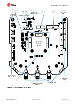
EVK-JODY-W3 - User guide
UBX-20030840 - R02
Board description
Page 17 of 29
Power supply source
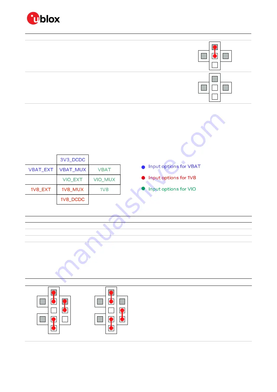
Jumper configuration
7 V – 24 V external power supply
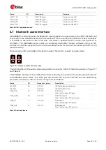
External supply (7 V – 24 V) must be connected to the power jack J100. The external supply
voltage is first converted to 5 V using a DC-DC on the EVK.
J100: Phoenix Contact 1721986
All input voltages supplied from individual sources
External supplies must be connected to the power jacks located on the bottom side of the
EVK for 3V3 (J101), 1V8 (J103) and VIO (J102).
J101-J103: Phoenix Contact 1721986
Table 5: Jumper settings for power supply selection for the EVK
4.3.2
Input voltage selection
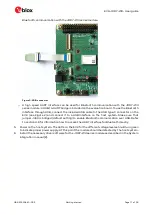
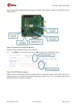
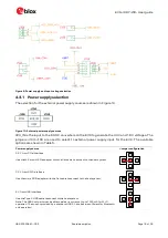
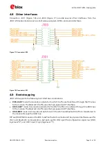
With reference to the power matrix shown in Figure 11, position jumpers J107, J108, J109, and J111
to select the appropriate input voltages for the module. The jumpers configure the input between DC-
DC generated voltages and the direct input voltage from the individual supplies.
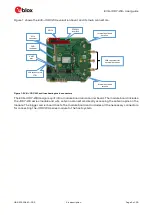
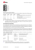
Figure 11 shows the jumper pins for configuring the input voltages described in Table 6.
Figure 11: Input voltage pins
Designator
Module supply
Source
VBAT_MUX
3V3
Can be connected to 3V3_DCDC or VBAT_EXT
VIO_MUX
VIO
Can be connected to VBAT, 1V8 or VIO_EXT
1V8_MUX
1V8
Can be connected to 1V8_DCDC or 1V8_EXT
Table 6: Input voltage options
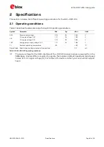
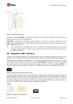
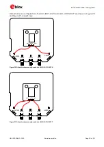
For the operation of EVK-JODY-W3, power supply jumpers must be set as explained in Table 5 and
Table 7. The first one selects the external power supply and the second one defines the voltage levels
to operate the module. Table 7 describes the different options to select the input voltages for the
module.
Jumper settings
Description / Voltage levels
VIO (3.3 V)
VIO (1.8 V)
Power supply using host interface (PCIe, SDIO or USB) or
single external supply (VEXT) and DC-DC generated
voltages. VIO voltage is derived from either 1V8 or VBAT.
•
3V3/VBAT – 3.3 V
•
1V8 – 1.8 V
•
VIO – 1.8 V or 3.3 V


