EVK-NINA-B4 - User guide
UBX-19054587 - R03
Interfaces and peripherals
Page 22 of 38
C1 - Public
5
Interfaces and peripherals
5.1
Buttons and LEDs
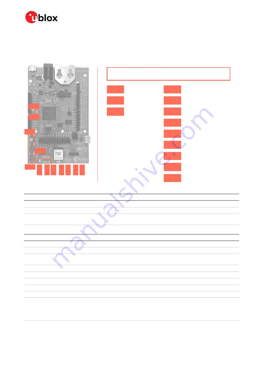
Figure 15: Position of the push buttons and LEDs on the evaluation board
Annotation
Function
Description
SW0
Reset button
Connected directly to the NINA RESET_N pin.
SW1
User button
Push button for application use. Connected directly to the NINA SWITCH_1 (GPIO_7) pin
SW2
User button
Push button for application use. Connected directly to the NINA SWITCH_2 (GPIO_18)
pin.
Table 9: EVK-NINA-B4 buttons
Annotation
Function
Description
Color
DS1
UART CTS LED
Connected to the NINA UART_CTS (GPIO_21) pin via jumper header J9
DS2
UART RTS LED
Connected to the NINA UART_RTS (GPIO_20) pin via jumper header J9
DS3
Interface MCU LED
Blinks on USB enumeration and activity, lit when the Interface MCU is
connected via USB
DS4
Interface MCU LED
Error LED
DS5
UART DTR LED
Connected to the NINA UART_DTR (GPIO_16) pin via jumper header J9
DS6
UART DSR LED
Connected to the NINA UART_DSR (GPIO_17) pin via jumper header J9
DS7
UART TXD LED
Connected to the NINA UART_TXD (GPIO_22) pin via jumper header J9
DS8
UART RXD LED
Connected to the NINA UART_RXD (GPIO_23) pin via jumper header J9
DS9
RGB LED
Connected to the NINA RED (GPIO_1), GREEN (GPIO_7) and BLUE (GPIO_8) pins
via jumper header J19. The RGB LED shows the status for the
u-connect applications.
☞
See the NINA-B4 data sheet [3] for additional information.
Table 10: EVK-NINA-B4 LED indicators
SW0
SW1
SW2
DS
6
DS
5
DS
1
DS
2
DS
7
DS
8
DS
9
DS3
DS4
Buttons and LEDs
SW0
Reset
User button
User button
SW1
SW2
DS3
Interface MCU LED
Interface MCU LED
Status LED
DS4
TXD LED
RXD LED
RTS LED
CTS LED
DTR LED
DSR LED
DS9
DS8
DS7
DS2
DS1
DS5
DS6


