EVK-VERA-P174 - User Guide
UBX-17048707 - R06
Board description
Page 9 of 30
3
Board description
This section describes the EVK-VERA-P174 evaluation board, the available connectors, and
configuration settings.
3.1
Block diagram
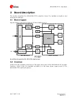
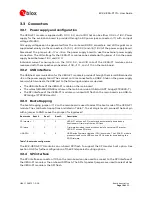
Figure 3 shows a general block diagram of the evaluation board.
Figure 3: Block diagram of the EVK-VERA-P174 evaluation board
3.2
Overview
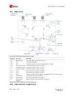
Table 5 lists the available connectors on the upper main board of the EVK-VERA-P174 and their
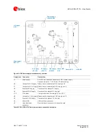
functions. Table 6 lists the available connectors on the lower power supply board of the
EVK-VERA-P174 and their functions.
VERA-P1
GNSS
SMA
SMA
SMA
8 MBit Flash
SPI
USB-to-UART
Bridge
UART
USB
Hub
USB-to-SPI
Bridge
Power Supply
9V ... 28V
USB
USB
USB & Power Board
VERA-P1 Main Board
Host Connector
& Pin Header
5V
3.3V
1.8V
1PPS

