EVK-IRIS-W10 - User guide
UBX-23007837 - R03
Hardware description
Page 14 of 43
C1-Public
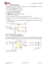
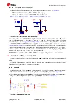
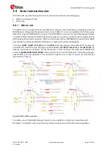
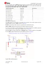
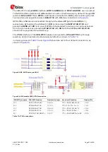
In this mode, the status of the USB-ID signal defines whether the EVB or IRIS-W10 module
works as either an OTG host (supply the voltage to a device board), or an OTG device. USB-ID
is connected to the ground or left floating, as shown in
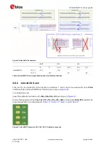
Figure 11: J72 schematic
3.1.1.4
VBUS-OUT (5V) connection on pin headers
VBUS-OUT (5 V) connections on the
J3
,
J4
,
J10
, and
J70
pin headers should only be used for
reference or verification. Otherwise, they can only supply a combined 500mA current and
should not be utilized in conjunction with USB-OTG Host mode.
3.1.1.5
mikroBUS slots 5 V positions
Intended for mikroBUS standard
5 V pins.
3.1.2
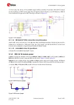
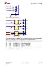
IRIS-W10 module power
+3V3
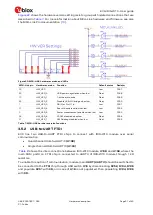
is supplied to IRIS-W10 through
VDD-IO
(
J96
) and
VDD
(
J97
), with resistors
R62
and
R35
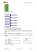
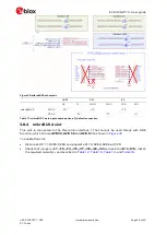
intended for current measurement, as shown in
and
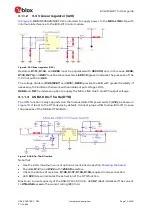
VDD-IO
can be supplied from the
+1V8
or
+VPA
module outputs through jumpers
J115
and
J116
(bottom side of the EVB).
R126
is needed for the current consumption sensing process.
Jumpers
J96, J115, and J116
should not be connected simultaneously.
Figure 12: VDD-IO current jumpers
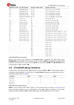
Figure 13: VDD current jumper
+3V3
VDD
J97
0R
0603
R35


