MAX-M5Q - Hardware Integration Manual
FTX-HW-13008
Objective Specification
Design
Page 16 of 40
3.3
Layout
This section provides important information for designing a robust GPS/GNSS system.
GPS/GNSS signals at the surface of the Earth are about 15 dB below the thermal noise floor. Signal loss from the
antenna to RF_IN pin of the module must be minimized as much as possible. When defining a GPS/GNSS
receiver layout, the placement of the antenna with respect to the receiver, as well as grounding, shielding and
jamming from other digital devices, are crucial issues requiring careful consideration.
3.3.1
Footprint and paste mask
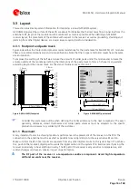
Figure 4 describes the footprint and provides recommendations for the paste mask for MAX-M5Q LCC modules.
These are recommendations only and not specifications. Note that the Copper and Solder masks have the same
size and position.
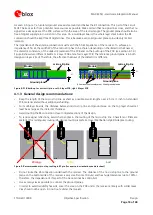
To improve the wetting of the half vias, reduce the amount of solder paste under the module and increase the
volume outside of the module by defining the dimensions of the paste mask to form a T-shape (or equivalent)
extending beyond the Copper mask. For the stencil thickness, see section 6.2.1
9.7 mm [382 mil]
1
0.
1
m
m
[
39
8
mi
l]
1.0 mm
[39.3 mil]
0
.7
mm
[27.
6
mi
l]
0.8 mm
[31.5 mil]
0.
65 m
m
[26.
6
mi
l]
1
.1
mm
[43.
3
mi
l]
0
.8
mm
[31.
5
mi
l]
Figure 4: MAX-M5Q footprint
Stencil: 150
µ
m
7.9 mm [311 mil]
12.5 mm [492 mil]
9.7 mm [382 mil]
0.
7 mm
[27.
6
mi
l]
0.
5 mm
[19.
7
mi
l]
0.
8 mm
[31.
5
mi
l]
0.
6 mm
[23.
5
mi
l]
4
Figure 5: MAX-M5Q paste mask
Consider the paste mask outline when defining the minimal distance to the next component. The exact
geometry, distances, stencil thicknesses and solder paste volumes must be adapted to the specific
production processes (e.g. soldering) of the customer.
4.1.1
Placement
A very important factor in achieving maximum performance is the placement of the receiver on the PCB. The
connection to the antenna must be as short as possible to avoid jamming into the very sensitive RF section.
Make sure that the RF critical circuits are separate from any other digital circuits on the system board. To achieve
this, position the module’s digital part towards the digital section on the system PCB. Exercise care if placing the
receiver in proximity to heat emitting circuitry. The RF part of the receiver is very sensitive to temperature, and
sudden changes can have an adverse impact on performance.
The RF part of the receiver is a temperature sensitive component. Avoid high temperature
drift and air vents near the receiver.

