SARA-G450 - System integration manual
UBX-18046432 - R08
System description
Page 22 of 143
C1-Public
1.5.3
Generic digital interfaces supply output (V_INT)
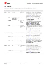
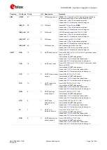
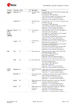
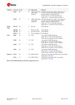
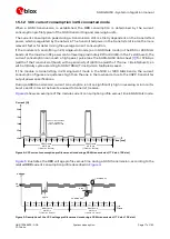
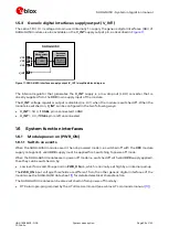
The same 1.8 V / 3 V voltage domain used internally to supply the generic digital interfaces (GDI) of
SARA-G450 modules is also available on the V_INT supply output pin, as described in
Baseband
processor
51
VCC
52
VCC
53
VCC
4
V_INT
LDO
Digital I/O
Interfaces
Power
Management
Unit
SARA-G450
Figure 11: SARA-G450 interfaces supply output (V_INT) simplified block diagram
The internal regulator that generates the V_INT supply is a low drop out (LDO) converter that is
directly supplied from the VCC main supply input of the module.
The V_INT voltage regulator output is disabled (i.e. 0 V) when the module is switched off. When the
module is switched on, V_INT can be configured in the two following ways:
V_INT = 1.8 V, if VSEL pin is connected to GND
V_INT = 3 V, if VSEL pin is left unconnected
1.6
System function interfaces
1.6.1
Module power-on (PWR_ON)
1.6.1.1
Switch-on events
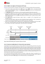
When the SARA-G450 modules are in the not-powered mode (i.e. switched off with the VCC module
supply not applied), valid VCC supply must be applied first, switching to power-off mode.
When the SARA-G450 modules are in power-off mode (i.e. switched off with valid VCC supply applied),
then they can be switched on by:
Low level for a valid time period on PWR_ON pin, which is normally set high by an internal pull-up
The PWR_ON input voltage thresholds are different from the other generic digital interfaces of the
module: see the SARA-G450 data sheet
for detailed electrical characteristics.
The SARA-G450 modules can be also switched on from power-off mode by:
RTC alarm pre-programmed by the AT+CALA command (see u-blox AT commands manual


