SARA-G450 - System integration manual
UBX-18046432 - R08
Design-in
Page 96 of 143
C1-Public
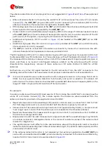
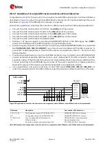
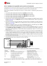
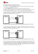
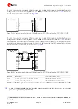
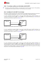
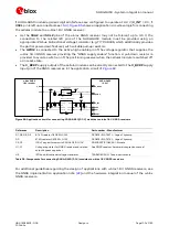
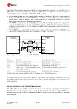
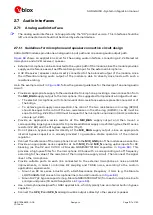
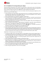
If a 3.0 V application processor (DTE) is used and module (DCE) generic digital interfaces are
configured to operate at 3.0 V (V_INT = 3 V, if VSEL pin is left unconnected; see
), the circuit
should be implemented as described in
TxD
Application Processor
(3.0V DTE)
RxD
RTS
CTS
DTR
DSR
RI
DCD
GND
SARA-G450
(3.0V DCE)
12
TXD
9
DTR
13
RXD
10
RTS
11
CTS
6
DSR
7
RI
8
DCD
GND
0
Ω
TP
0
Ω
TP
21
VSEL
Figure 57: UART application circuit with partial V.24 link (3-wire) in the DTE/DCE serial interface (3.0 V DTE / 3.0 V DCE)
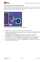
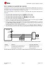
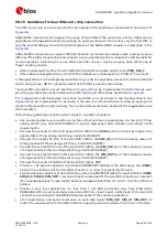
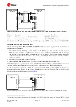
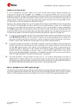
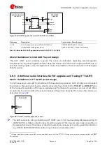
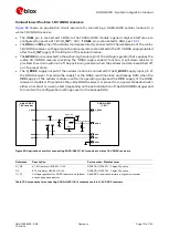
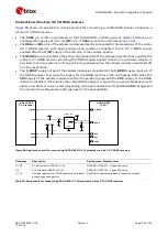
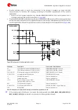
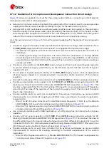
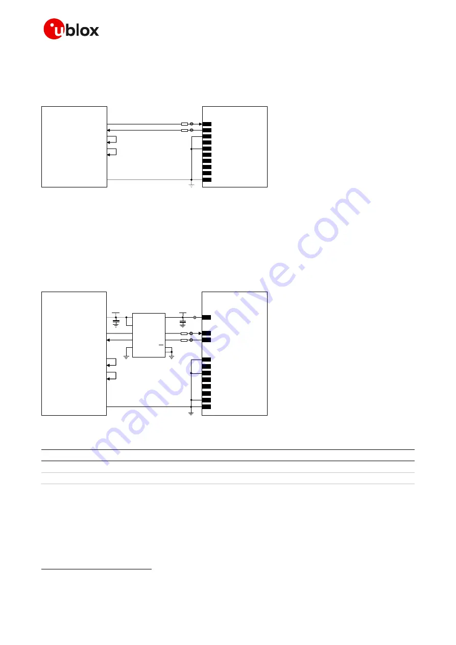
If a 3.0 V application processor (DTE) is used and module (DCE) generic digital interfaces are
configured to operate at 1.8 V (V_INT = 1.8 V, if VSEL pin is connected to GND; see
), then it is
recommended to connect the 1.8 V UART interface of the module (DCE) by means of appropriate
unidirectional voltage translators using the module V_INT output as the 1.8 V supply for the voltage
translators on the module side, as described in
4
V_INT
TxD
Application Processor
(3.0V DTE)
RxD
DTR
DSR
RI
DCD
GND
SARA-G450
(1.8V DCE)
12
TXD
9
DTR
13
RXD
6
DSR
7
RI
8
DCD
GND
1V8
B1
A1
GND
U1
VCCB
VCCA
Unidirectional
voltage translator
C1
C2
3V0
DIR1
DIR2
OE
VCC
B2
A2
RTS
CTS
10
RTS
11
CTS
TP
0
Ω
TP
0
Ω
TP
21
VSEL
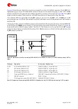
Figure 58: UART application circuit with partial V.24 link (3-wire) in the DTE/DCE serial interface (3.0 V DTE / 1.8 V DCE)
Reference
Description
Part number – Manufacturer
C1, C2
100 nF capacitor ceramic X7R 0402 10% 16 V
GRM155R61A104KA01 – Murata
U1
Unidirectional voltage translator
SN74AVC2T245
17
- Texas Instruments
Table 35: Parts for UART application circuit with partial V.24 link (3-wire) in DTE/DCE serial interface (3.0 V DTE / 1.8 V DCE)
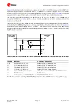
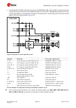
☞
If only the TXD and RXD lines are provided, data delivered by the DTE can be lost with module
power saving enabled by AT+UPSV=1
17
Voltage translator providing partial power-down feature so that the DTE 3.0 V supply can be also ramped up before V_INT
1.8 V supply

