


EVK-R2 - User Guide
UBX-16016088 - R10
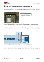
Starting up
Page 13 of 27
DIL B2B J301
DIL B2B J300
Signal Name
Pin N° Pin N°
Signal Name
Signal Name
Pin N° Pin N°
Signal Name
Not connected
2
1
GND
Not connected
2
1
GND
Not connected
4
3
V_BCKP
Not connected
4
3
Not connected
Not connected
6
5
Not connected
Not connected
6
5
Not connected
GND
8
7
GND
VCC
8
7
VCC
GND
10
9
GND
VCC
10
9
VCC
DTR
12
11
DCD
Not connected
12
11
Not connected
CTS
14
13
RTS
SIM_IO
14
13
VSIM
RXD
16
15
TXD
SIM_RST
16
15
SIM_CLK
DSR
18
17
RI
SDIO_CMD
18
17
SDIO_D0
Not connected
20
19
Not connected
SCL
20
19
SDIO_CLK
Not connected
22
21
HOST_SELECT
Not connected
22
21
SDA
Not connected
24
23
GPIO5
Not connected
24
23
Not connected
Not connected
26
25
GPIO4
RESET_N
26
25
Not connected
Not connected
28
27
Not connected
MIC_BIAS
28
27
MIC_GND
SDIO_D2
30
29
PWR_ON
Not connected
30
29
Not connected
GPIO3
32
31
GPIO2
Not connected
32
31
Not connected
Not connected
34
33
GPIO1
SPK_N
34
33
SPK_P
V_INT
36
35
Not connected
Not connected
36
35
Not connected
Not connected
38
37
SDIO_D1
Not connected
38
37
Not connected
Not connected
40
39
SDIO_D3
Not connected
40
39
Not connected
GND
42
41
GND
GND
42
41
Not connected
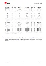
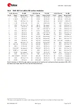
Table 7: Pin-out of the 42-pin Dual-In-Line Board-to-Board connectors (J301, J300) available on the adapter board ADP-R2
of the EVK-R2 evaluation kit for LARA-R2 series modules
☞
The pins / interfaces that are not supported by a specific LARA-R2 module product version should
not be driven by an external device (see the LARA-R2 series Data Sheet
and the LARA-R2 series
System Integration Manual
for the features supported by each LARA-R2 module product
version).
1.7
Software installation
The USB drivers are available with the EVK-R2. Executable files can be downloaded from
and saved to any location on the computer hard drive. The
installation can be started by running the executable file on a computer with the Windows operating
system.
1.8
Board setup
1.
Insert a SIM card into the SIM card holder (J300 on the EVB).
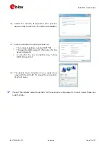
2.
Connect a cellular antenna provided with the evaluation kit box to the Primary cellular antenna
SMA connector on the ADP-R2 (ANT1, RF input/output for transmission and reception of
LTE/3G/2G RF signals)
3.
Connect a cellular antenna provided with the evaluation kit box to the Secondary cellular antenna
SMA connector on the ADP-R2 (ANT2, RF input for the reception of the LTE RF signals as per


