


EVK-R2 - User Guide
UBX-16016088 - R10
Starting up
Page 14 of 27
Down-Link Rx diversity). Place the secondary cellular antenna far enough from the primary
cellular antenna (should be more than 20 cm).
4.
If the GNSS functionality is required, connect the GNSS antenna provided with the evaluation kit
box to the GNSS antenna SMA connector on the EVB. Place the GNSS antenna in a location with
a good view of the sky.
☞
Since the interface to the GNSS module is not supported by LARA-R204-02B-00 /
LARA-R211-02B-00 / TOBY-R200-02B-00 / TOBY-R202-02B-00 modules, the following changes
are needed on the ADP-GNSS to appropriately provide supply to the GNSS:
o
R106 = 0R, instead of not installed
o
R107 = Do not install, instead of 0R
5.
Connect the AC / DC +12 V power adapter provided with the evaluation kit box to the 9 – 18 V
Power Input connector (J400 on the EVB). LED DL401 lights blue.
6.
Be sure to provide a jumper socket on the Cellular VCC supply jumper (J404 on the EVB). This
provides the connection from the 3.8 V output of the supply circuit on the EVB to the VCC input
of the module.
7.
To enable the board power supply, turn the Main power switch (SW400 on the EVB) to the ON
position. LED DL400 lights green. The cellular module switches on.
☞
If the cellular module has been powered off by the AT+CPWROFF command, press the Cellular
Power-On button (SW302 on EVB) or the Cellular Reset button (SW303 on EVB) to switch on the
module again.
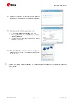
8.
For communication via the cellular module’s USB interface, connect a USB cable to the Cellular
native USB connector (on ADP-R2). LED DS100 on ADP lights blue.
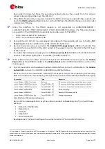
After the end of the module boot, the COM ports listed in
USB driver (details as the numbering of the ports can be seen via the Windows Device Manager)
5
:
Parameter
Type
Remarks
u-blox Modem USB1 AT and data
Modems
AT command interface and data communication
u-blox Modem USB2 AT and data
Ports (COM & LPT)
AT command interface and data communication
u-blox Modem USB3 AT and data
Ports (COM & LPT)
AT command interface and data communication
u-blox Modem USB4 GNSS
Ports (COM & LPT)
GNSS tunneling
u-blox Modem USB5 SAP
Ports (COM & LPT)
Remote SIM Access profile
u-blox Modem USB6 Primary Log
Ports (COM & LPT)
Diagnostic purpose
Table 8: Cellular USB interface configuration
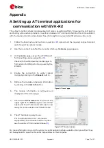
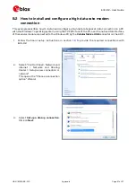
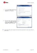
Run an AT terminal application (e.g. the u-blox m-center tool) selecting an AT port, with these
settings:
Data rate: 115,200 bit/s
Data bits: 8
Parity: N
Stop bits: 1
Flow control: HW
See Appendix
for how to configure the u-blox m-center AT terminal for Windows.
5
A message of “driver installation fail” may appear on Windows if the USB cable has been connected before the end of the
module boot, but this can be ignored as the normal operating functionality of the module will be available anyway after the end
of the module boot.


