


EVK-R2 - User Guide
UBX-16016088 - R10
Starting up
Page 8 of 27
1.3
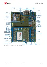
Switches, jumpers and buttons
Function
Description
Name Board
Main Power Switch
Power on / off of the whole evaluation kit
SW400 EVB
Cellular VCC
Jumper socket to provide the 3.8 V supply to the cellular module VCC input
J404
EVB
Cellular Power-on
Push button to switch-on the cellular module
SW302 EVB
Cellular Reset
Push button to reset the cellular module
SW303 EVB
Cellular UART detach Slide switch to attach / detach cellular module UART from USB / RS232 connectors:
when detached, UART signals available only on DIL B2B connector on ADP board
SW401 EVB
Cellular UART routing Slide switch to select cellular module UART routing on USB or on RS232 connector
SW403 EVB
Cellular GPIO detach
Slide switch to attach / detach the cellular module GPIOs, SIM_DET from peripherals:
when detached, the signals are available only on the DIL B2B connector on ADP board
SW300 EVB
Cellular GNSS detach Slide switch to attach / detach the cellular module to the GNSS module (GPIO2-3-4):
when detached, the signals are available only on DIL B2B connector on ADP board
SW304 EVB
GNSS V_BCKP
Slide switch to connect / disconnect backup battery to V_BCKP pin of the GNSS
module
SW204 EVB
Table 1: EVK-R2 switch and button descriptions
1.4
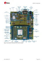
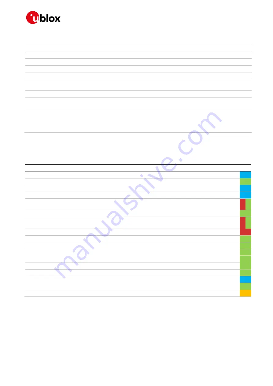
LEDs
Function
Description
LED # Board
Color
Main Power
Power supply plugged in the 9 - 18 V Power Input
DL401 EVB
Cellular VCC
Cellular module supplied. Main Power Switch must be switched on
DL400 EVB
Cellular native USB
USB cable plugged in the Cellular native USB connector
DS100 ADP-R2
Cellular USB
USB cable plugged in the Cellular USB connector for UART access
DL501 EVB
Cellular USB / UART
Green light is activated when UART is routed to the Cellular USB connector
Red light blinks at UART TX or RX data on the Cellular USB connector
DL403 EVB
Cellular UART detach UART signals are available only on the DIL B2B connector on ADP board
DL404 EVB
Cellular RS232 / UART Green light is activated when UART is routed to Cellular RS232 connector
Red light blinks at UART TX or RX data on the Cellular RS232 connector
DL405 EVB
Cellular RI indicator
RI line turns ON (active low)
DS501 EVB
Cellular CTS indicator CTS line turns ON (active low)
DS500 EVB
Cellular GPIO1 indicator Green light is activated when cellular GPIO1 is high
DS107 EVB
Cellular GPIO2 indicator Green light is activated when cellular GPIO2 is high
DS105 EVB
Cellular GPIO3 indicator Green light is activated when cellular GPIO3 is high
DS109 EVB
Cellular GPIO4 indicator Green light is activated when cellular GPIO4 is high
DS103 EVB
GNSS VCC supply
GNSS module supply is turned ON
DS118 ADP-GNSS
GNSS USB
USB cable plugged in GNSS USB connector
DS124 ADP-GNSS
GNSS Timepulse
Pulses at 1 Hz when valid GNSS fix
DS121 ADP-GNSS
Cellular / GNSS DDC
Cellular / GNSS module communication over the DDC (I
2
C) interface
DS132 ADP-GNSS
Table 2: EVK-R2 LED descriptions


