background image

18

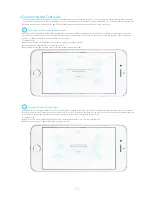
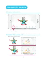
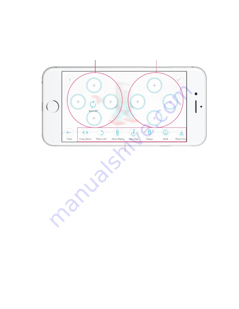
If you have not configured the remote control, you can press the Settings button on the top right corner to enter the Remote Control 

Configuration page. In this page, all of the movements that you have added to the model will show up on the Movement bar at the bottom of 

the page.

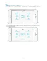
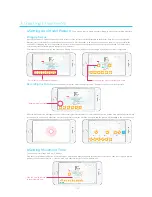
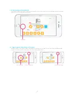
Drag the Movement icon and place it onto a certain button on the remote control. If a movement has already been added to that button, the 

new movement you dragged will replace the existing one.

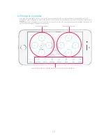
b.Editing the Controller

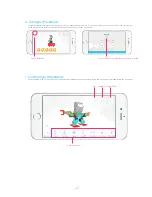
You can drag the Movement icon and place it onto any button on the remote control. 

Remote control buttons

Remote control buttons

Summary of Contents for Jimu

Page 1: ...APP Instructions ...

Page 2: ...y Methods 10 C Jimu APP Getting the Jimu App 11 Using Ubtech Account to Log in 11 D Learn to Build Tutorial 12 Offcial Models 12 E Wireless Connection Wireless Connection Process and Connection Requirements 14 F Remote Control 17 G Movement Introduction Creating Movements 19 Movement Principle 19 Creating Movements 20 H Creating Selecting Category 23 Adding Photos 23 Naming 23 I Sharing and Discov...

Page 3: ...ications Processor STM32F070 Memory 4M Communication dual mode Bluetooth 3 0 4 0 BLE EDR 1 Main Control Box Battery Power Indicator Located on the left side of the main control box it indicates the current power status of the main control box Statuses as displayed by the indicator are as follows Red charging Green fully charged Flashing green operating Charging Interface Used to charge the control...

Page 4: ...n control box Install the replacement battery into the controller and then secure the plugs Detaching the Battery 2 Battery Battery Specifications Operating voltage DC 6 5 9 6 V Operating current 1 2 A Battery capacity 1 200 mAh Battery parameter Lithium polymer battery Operating temperature 23 113 F 5 45 C Remove the plugs Gently lift up the battery Remove the battery 2 ...

Page 5: ...Changing Servo ID for more details Slots There are 5 slots on the servo with which the rudder can be spliced namely ABCDE For more details please see Assembly Introduction Splicing Servos are like human joints They are the keys for the Jimu robot to perform movements Servo external view Servo ID 3 Servos 3 ...

Page 6: ...nect controller and servo or servo and servo 3 pin ports Rotatable Rudders The rudders of the servo can rotate and it can also be spliced with slots indicates different splicing directions When is aligned with the scale the angle of the rotatable rudder is 0 For more information regarding the use of servo rudders and other components assembly please see Assembly Introduction Splicing When is align...

Page 7: ...ents through plugs and attachments The decorating pieces are the cover of the model and give it a more attractive appearance 5 Decorating Pieces Straighten the rudder and align the component Push the right side of the component as indicated by the arrow until you hear a popping noise Adjust the other side When you hear the same popping noise the component has been successfully installed Pop Pop Ge...

Page 8: ...er switch to the Main control box Turn on off the power using the power switch 6 Power Switch Note Fasteners come in different shapes lengths and sizes Fasteners can integrate decorating pieces connectors the controller and servos together through holes 7 Decorating Piece Fasteners 6 ...

Page 9: ...gy and commands between the controller and servos The assembly tool can help you install and remove components making the building process of your model simpler and easier The end of the assembly tool is a clip It can clip onto connectors to remove them from the components or install them into the components 8 Connecting Cables Use method 9 Assembly Tool 7 ...

Page 10: ...dders Rudders are rectangular structures projecting from components The symbols are used to indicate the different directions Assembly Introduction 8 圆孔位 十字孔位 The slot is a groove in components which usually appears on connectors and servos When a component has multiple slots the ABCDE naming method will be used to distinguish them ...

Page 11: ...the rudder correspond with different splicing directions of slots Different splicing directions can yield different structures Example of connecting other components with rudders 2 If a component has multiple slots it can be assembled into different structures 2 Assembly Methods 9 ...

Page 12: ... Main control box through 2 pin ports to turn on off the Main control box Connect the controller with servo through 3 pin holes Connect servo with servo through 3 pin ports b Integration Integration refers to the method of assembling different components through fasterners c Connection Connection refers to the assembly method of connecting the Main control box with servos servos with servos the Ma...

Page 13: ...oid App Store or other App stores Download and install Jimu app c Go to http www ubtrobot com app asp in the browser download the software and install it 2 Using Ubtech Account to Log in Users can use the Ubtech account to log in and use our products including the Alpha1s App Alpha 2 App and Jimu app Within the Jimu app you can select Email Mobile phone or Third party account login to register a U...

Page 14: ...The Components section illustrates the appearance of all components and their functions to the users The Assembly section describes the key parts of the components and how to assemble them The Connection section covers the connection rules and procedures of Jimu The Movement section introduces the principles and processes of movement design while the Programming section the functions and processes...

Page 15: ...of the model in 360 on your mobile phone You can also use the Dynamic Drawings function and follow the 3D interactive animation step by step to build the model b After building the actual model you can connect your actual model by pressing the Connect button on the Model Details page see Wireless Connection for details 13 ...

Page 16: ...d the Bluetooth device then find the renamed Bluetooth device For Android devices please find the device s MAC address 1 Wireless Connection Process and Connection Requirements Wireless Connection a Switching on the Main control box Power Switch the power button from the off position to the on position when the Main control box s power indicator is flashing green it means that it has been successf...

Page 17: ...t error messages Then reconnect Troubleshooting Check whether the model has been completed according to the steps in Build Check whether changes has been made to the model Check whether the app has been connected to the wrong model or controller The number of servos should be consistent e Connecting the Controller 1 In addition to comparing the number of servos the app will also compare to see if ...

Page 18: ...ed at over 50 If battery power is lower than 50 upgrading cannot be completed and the wireless connection will be disconnected After your mobile device is successfully connected to the controller you can view the battery power level of the model and the connection status on the connected Model Details page The servo firmware versions should be consistent 3 ...

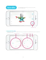
Page 19: ...ng a video game Controller Enter the remote control page With the configured remote control you can directly press the corresponding buttons to have the robot perform the corresponding movements a Using the Controller Remote control icon Stop Pause Edit Remote control buttons Remote control buttons ...

Page 20: ...the model will show up on the Movement bar at the bottom of the page Drag the Movement icon and place it onto a certain button on the remote control If a movement has already been added to that button the new movement you dragged will replace the existing one b Editing the Controller You can drag the Movement icon and place it onto any button on the remote control Remote control buttons Remote con...

Page 21: ...ne posture to another one within a period of time The movement can be defined through time setting and posture adjustment Beginning posture Create new movement button Ending posture Beginning time slider Grag the green spot to set ending time Before building a new movement you might need to know the movement principle of Jimu 19 ...

Page 22: ...u can now configure the servo angle by rotating the control components A Record Movement icon will appear on the movement axis after the Jimu robot is connected Click the icon and the Jimu robot will automatically loosen the joint You can now adjust the robot into the posture you want Click the icon again and the posture will be added to the movement axis The movement time range is 80 ms 5 000 ms ...

Page 23: ...the entire movement c Previewing a Movement In Edit Servo mode you can copy the current movement And the insert button at the top right corner in movement programming page will be activated You can select another posture and insert the posture copied earlier behind this d Copynig and Inserting a Posture Edit Servo mode Click the Copy button Play button Click the Paste button ...

Page 24: ...in the Movement Bar by their icons and the name of the movements e Saving a Movement After selecting a specific movement the control button will appear You can play pause stop the movement or edit and delete the movement f Controling a Movement Save movements Input a name of the movement that needs to be saved Saved movements Play Stop Pause Edit Delete ...

Page 25: ...model Animal Machine Robot Others When you share your models with the community model categories help other users to find your models 2 Adding Photos The Jimu app does not support creating 3D models within the app Because it is different from the official models you will need to add a photo for your model You can select one from the photo album or directly take a picture of the model 3 Naming Assi...

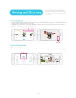
Page 26: ...n for your model After adding the necessary information click the upload button at the top right corner to upload the model to the community After successfully uploading you can also share this model to other social platforms a Sharing Models Enter the community page from the menu The models in the community are categorized based on different categories of models uploaded by users You can see the ...

Page 27: ...e app must match If they do not match it will affect the robot s action 3 Ensure that the battery is not getting too low 4 Check if all the connecting parts are properly assembled Once they are assembled in place you should hear a clap sound 2 APP Q The official model cannot be downloaded A 1 Check if there are any Internet connection issues 2 Ensure your cell phone has enough storage space 3 The ...

Page 28: ...s according to the reported errors on the topological graph If there are errors reported about several servo motors please check if the cables are properly connected to the ports on the main control box Q The app displays duplicate Servo IDs A 1 Check if you have bought multiple hardware products and the same ID has been used more than once You can just find the ID and replace it 2 Check if you ha...

Reviews: