background image

Mr Bot 280 


Step 4 


Your  semi-assembled  printer  should 

look like in the photo. 


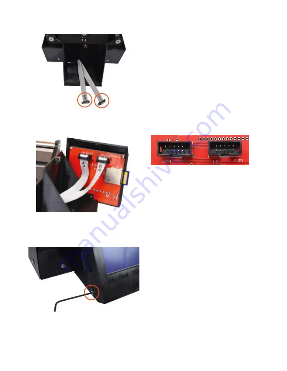
Step 5 


Connect  the  numbered  ribbon  cables 

to  the  corresponding  numbered  plugs 

on the back of the LCD display. 


Step 6 


Screw  the  pre-assembled  part  of  the 

LCD  display  to  the  printer's  sub-

assembly  with  the  three  M3x6mm 

screws (4). 


Summary of Contents for MR BOT 280

Page 1: ...Quick Start Guide UBUILD 3D MR BOT 280...

Page 2: ...ene Open the box and remove the protective cardboard with polyethylene foam Lift the printer with your hands as shown below Setting up the printer After removing the packaging to operate your printer...

Page 3: ...ay What you will need for the assembly 1 Allen key 2mm 2 Allen key 2 5mm 3 LCD rear panel 1x 4 LCD display pre assembled 1x 5 Rectangular sheet metal 6 M3x6mm button head screws 3x 7 M4x6mm button hea...

Page 4: ...the rectangular sheet metal Step 2 With the M3x6mm half rounded head screws 2 screw the LCD s rear panel 5 with the rectangular sheet metal Step 3 Locate where to attach the sub assembly under the pri...

Page 5: ...uld look like in the photo Step 5 Connect the numbered ribbon cables to the corresponding numbered plugs on the back of the LCD display Step 6 Screw the pre assembled part of the LCD display to the pr...

Page 6: ...ng the spool holder and teflon tube brackets What you will need for the assembly 1 Teflon tube bracket 1x 2 Teflon tube bracket with pneumatic connector 1x 3 Teflon tube 1x 4 Allen key 2 5mm 5 M4x6mm...

Page 7: ...screw the teflon tube brackets to the right of the printer The bracket with the pneumatic connector goes to the lower position see circle Step 2 Pass the tube from the top bracket and slide it down S...

Page 8: ...the extruder s pneumatic connector Step 5 Mount the spool holder First diagonal and up as in the photo so the top bracket of the spool holder passes from the center hole and then slide down so the tw...

Page 9: ...e spool holder you need to adjust the correct distance between the nozzle and the printing surface What you will need 1 Calibration sheet 1x Note The first time you will use the calibration sheet reme...

Page 10: ...ears Step 2 To access the menu press the LCD s knob and turn clockwise or counterclockwise Step 3 Access in the basic menu you will find the Calibration downwards Select it Select the Yes command and...

Page 11: ...The properly adjusted distance between the nozzle and the print surface is when you feel a slight friction of the nozzle pressing the Calibration sheet When you select the appropriate distance press...

Page 12: ...the material toward the teflon tube so that the motor can snap it more easily and at the same time press the LCD s knob Wait a few seconds until you see some of the material coming out of the nozzle...

Reviews: