background image


SERVICE MANUAL 


UCHIDA YOKO CO., LTD., TOKYO, JAPAN


V2.00 


Summary of Contents for AeroCut nano+

Page 1: ...SERVICE MANUAL UCHIDA YOKO CO LTD TOKYO JAPAN V2 00 ...

Page 2: ... 5 3 Feed belt Unit 17 6 Adjustment 18 6 1 Feed sensor position 18 6 2 Double feed sensor adjustment 26 6 3 Sensitivity of Cutmark sensor 27 6 4 Guillotine angle 28 6 5 Cutting location Guillotine 28 6 8 PCB CPU board setting 30 7 Program update 31 7 1 Outline 31 7 2 Connecting software install 32 7 3 Touch panel update 39 7 4 PCB CPU board update 42 8 Cleaning greasing 48 9 Recommended replacemen...

Page 3: ...AeroCut nano SERVICE MANUAL 3 Record of change No Date Contents of change Expected date to change ...

Page 4: ...ANUAL 4 1 Installation a Caster b Feed table Please be sure to lock a caster brake C Stacker and Waste box Unlock Lock Feed table Hex key Bolts x3 M4x8 Long stacker Waste box Card stacker Stacker end Business card partition ...

Page 5: ...UAL 5 Bolts d Electric power e In case of tabletop use Remove the bottom frame connecting bolts Put the machine on a table not to cover the waste chute Bottom frame AC 100 240V 50 60Hz 100W Electric power cord Lock Waste chute ...

Page 6: ...lades Timing belts 2 General instruction a Caution b Necessary tools C clip ring pliers Maintenance kit c Factory setting Factory setting sheet is attached inside of the front cover To replace slitter blades Program update tool Pipe For slitters To replace slitter blades ...

Page 7: ...AeroCut nano SERVICE MANUAL 7 Disconnect the connector for the touch panel Touch panel Slope Sensor cover d Remove covers ...

Page 8: ...r switch DC power supply PCB CPU board Feed table motor Fan motor Suction Fan motor Blow Feed sensor Feed belts Guillotine Cutter Guillotine motor Micro switch Feed table lower limit Micro switch Cover open Main motor Guillotine switch Timing belt Feed table stay Carrying roller Cutmark sensor Origin sensor Double feed sensor Feed motor ...

Page 9: ...TROL screen 3 2 Maintenance screen Press and buttons are not shown one by one to enter password entry mode Enter the service password Home screen Operation manual 5 1 Manual control screen MANUAL CONTROL screen Home screen Press once A button is not shown MANUSET screen ...

Page 10: ...AeroCut nano SERVICE MANUAL 10 SERVICE MENU screen Page 11 LANGUAGE screen Page 12 MANUAL OPERATION screen Page 11 SPEED screen Page 12 INPUT DATA CHECK screen Page 12 ...

Page 11: ...e times Operation time of Feed table hours minutes Go to MANUAL OPERATION screen Go to LANGUAGE screen This is to set either mm or inch as the measurement input unit 3 4 MANUAL OPERATION screen Carrying roller will rotate Carrying roller will rotate Continuous Carrying rollers will rotate at input length mm Fan motor Blow will be turned ON Fan motor Suction will be turned ON Go to INPUT DATA CHECK...

Page 12: ... thickness and speed 160 g 4 160 280 g 3 280 g 2 3 6 INPUT DATA CHECK screen Sensor Switch signals can be checked Origin sensor Cutmark sensor Feed sensor Invalid Micro switch Feed table lower limit Double feed sensor Guillotine switch Micro switch Cover open 3 7 LANGUAGE screen Languages on the touch panel can be changed Some languages are not selectable Some languages require Passwords 0 006 0 1...

Page 13: ...e the guillotine to chop jammed paper If the Main motor doesn t rotate slow down the speed The main motor has more torque as the speed becomes slower If paper is still remaining after process and remove the slitter cover and pick up the jammed paper After removing the jammed paper put the slitter cover and reset SPEED Slitter cover Screwdriver Screws Length 130mm 5 or less MANUAL CONTROL screen MA...

Page 14: ... If paper jam often occurs make sure that paper strip is not left in the indicated sections Inside of Slitter head Eject roller Origin sensor Carrying roller Feed belt The path between the feed belt to the carrying rollers Origin sensor ...

Page 15: ...nt of parts 5 1 Guillotine Check if the locating metal plate is in contact with the cutter unit This will be a mark for reattachment Remove cover and screws Remove Guillotine Do not loosen these screws Locating metal plate Locating metal plate ...

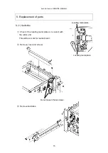
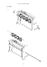
Page 16: ...AeroCut nano SERVICE MANUAL 16 5 2 Slitter ...

Page 17: ...AeroCut nano SERVICE MANUAL 17 5 3 Feed belt Unit Remove screws and cover Disconnect the harness Feed belt unit can be removed after bolts are removed Cover Connector Feed belt unit ...

Page 18: ...wer MANUAL CONTROL screen SPEED screen Standard Value Input 10 in case paper is too heavy to feed There will be possibility of double feed if paper is too thin In this case input 5 Ensure that LONG BLOW is shown on the screen There is possibility of empty feed Standard Value ...

Page 19: ...ition of a hole in below picture when attaching the feed belt unit It is factory setting if Feed belt unit is attached so that a small hole contacts a big hole Hole position Status Default FactorySetting Parallel to Guide Effectiveness of Aligner High Low None Guide Hole ...

Page 20: ...L 20 c Feed area mechanical adjustments 1 Lower Blower position Adjust the height by loosening screws Note Do not remove screws because blower will drop Blower Blower base Friction surface Blower base Range of Value H 0 5 1 0mm ...

Page 21: ...AeroCut nano SERVICE MANUAL 21 2 Separator position Separator Range of Value H 0 5 1 0mm Separator must be placed on higher position than friction surface Adjust the height by loosening screws ...

Page 22: ...position Adjust bolts This will be a mark for reattachment Lift and fix Feed belt unit with 2mm thick paper inserted as above figure Ensure that it is parallel to the Feed guide by sight Adjust the height by loosening screws Feed guide Feed belt unit ...

Page 23: ...or position When the feed table is upper dead point the proper gap between the feed table and the feed belt is 2 0 5mm 0 08 0 02 Loosen the screws and adjust the position of the feed sensor properly Feed table Feed sensor Screws Feed belts unit ...

Page 24: ...ts replacement etc the basement can be attached parallel by pressing the base against Locating metal plate Ensure that the basement is put on Locating metal plate when you detach it Please detach this part below in case that the upper surface of the basement is not parallel Locating metal plate Do not loosen this screw ...

Page 25: ...roCut nano SERVICE MANUAL 25 Settle a reference from two delivery rollers and adjust parallelism of the base with tolerance within 0 3 mm between A and B Difference between A and B should be within 0 3 mm ...

Page 26: ...chine does not detect double feed on the first fed sheet The machine detects double feed when the amount of the transmitted light of the second sheet and later is less than the reference The sensitivity of the double feed detection can be adjusted Operation manual 4 Adjustments The sensor reads 5mm from the edge of the top margin It is not recommended to print on this area Paper feed direction 5mm...

Page 27: ...LED turns off when a paper with a cut mark is put underneath the sensor Note The Cut mark sensor utilizes infrared light Depending on print the ink or toner might reflect the infrared light and cause the cut mark sensor not working properly Note Please make sure to print the whole of cutmark if not machine can t cut first cut correctly When the sensor detects black color the light is turned off LE...

Page 28: ...ating metal plate contacts to the guillotine unit 6 5 Cutting location Guillotine Home screen MANUAL CONTROL screen ADJUST screen Input the difference between the MANUSET input value and the actual cut size Stretch or shrink Between Cutmark and 1st cut Between paper edge and 1st cut Reset to default value Screws Screws Locating metal plate Locating metal plate ...

Page 29: ... one by one The buttons are not shown After the confirmation screen the default value will be overwritten To return the default values to the factory setting values Input the factory setting values to SERVICE MENU screen and Page 11 The factory setting values are shown on a sheet attached inside of the front cover Page 6 ...

Page 30: ... while in operation and adjust VR1 to 0 100V while not in operation All switch to left Switch only No 2 to right Double feed detection sensor VR7 must be fully turned counterclockwise VR5 does not require any adjustment VR6 to adjust the sensitivity that can be referred in service mode VR4 VR3 VR1 VR2 VR7 VR6 ...

Page 31: ...e screen when the machine power is turned on CPU version Touch panel version PCB CPU board update Page 42 Touch panel update Page 39 USB cable Included in Maintenance kit Connecting software Included in Maintenance kit Windows PC Transfer tool Included in Maintenance kit Update program Update program Windows PC Connecting software Included in Maintenance kit ...

Page 32: ...200 MHz processor or more Memory 128 MB or more 256 MB or more Hard disk space 600 MB or more 100 MB or more Display 1240 768 or more 4096 colors or more 1024 768 screen minimum 800 600 screen Interface USB port USB port b Confirmation of Accessories DISK1 will not be used for installation It contains files such as AVR related instruction manuals Please refer to them when needed USB cable 1 A B TY...

Page 33: ...D DVD drive and install it according to the following procedure The procedure below is for WINDOWS XP Double click on GTWIN gtwin_setup exe of the CD DVD Next Next Next Enter your name company name and the serial number The serial number is written in GTWIN serial_number txt Yes Next Next Select the language ...

Page 34: ...AeroCut nano SERVICE MANUAL 34 No Finish Select Yes to reboot automatically Select No to reboot manually ...

Page 35: ...oCut nano SERVICE MANUAL 35 d How to install AVR STUDIO For PCB update The procedure below is for WINDOWS XP Double click on AVR_TOOL AvrStudio4Setup exe of the CD DVD Next I accept Next Next Next Install ...

Page 36: ...AeroCut nano SERVICE MANUAL 36 Next is the update of AVR STUDIO Double click on AVR_TOOL AVRStudio4 18SP3 exe of the CD DVD Finish Next Finish ...

Page 37: ...AeroCut nano SERVICE MANUAL 37 Next is the installation of WINAVR Double click on AVR_TOOL WinAVR 20100110 install exe of the CD DVD Select a language OK Next I Agree Next Install Finish ...

Page 38: ...AeroCut nano SERVICE MANUAL 38 Close the Window ...

Page 39: ...rsion which means Version 1 00 Save this data in a folder of your choice in your computer and upgrade the version as follows Remove the unit cover and connect the USB cable provided with the unit to the back of the touch panel as shown below Turn on the power supply If the installation of the USB driver is necessary at this point install the driver using DISK2 which contains the driver in the USB ...

Page 40: ...k on Open Existing File Select the folder in which you saved our screen data select a file with a file extension of IOP Select File Transfer COM Settings USB GT and click OK This setting is necessary once after installation Next Finish Select where you saved the IOP file sent from us ...

Page 41: ...nd click OK to start transferring If asked to replace existing data click Overwrite all It takes several minutes to transfer the data After your installing updated software the direction you can see the below will remain on the touch panel After seeing that words on the screen turn off the machine and turn it on again ...

Page 42: ...and upgrade the version as follows Remove the cover at the bottom of the front of the unit Connect AVRISP mkⅡ provided with the unit to CN7 of the CPU Board and connect the USB cable to the computer If the installation of the USB driver is necessary at this point install the driver following the procedure below The procedure below is for WINDOWS XP Change The following folder is selected by defaul...

Page 43: ...AeroCut nano SERVICE MANUAL 43 Start up the computer and double click on Start Program Atmel AVR Tools AVR Studio 4 Click on Cancel Next Finish ...

Page 44: ...t to the Selected AVR Programmer Select AVRISP mkⅡ for Platform Select USB for Port click on Connect If the following warning appears on the screen AVRISP mkⅡfirmware upgrade is necessary Click on OK If the warning does not appear on the screen skip to ...

Page 45: ...on Start Upgrade Disconnect the USB cable of AVRISP mkⅡand connect it again After that click on OK If AVR STUDIO has shut down return to and conduct the operation again Click on Main tab select the Atmega2560 for Device and Signature Bytes ...

Page 46: ...Hz for ISP Freq click on Write and click on Close After clicking on Program tab select the folder where the file was initially saved as the save location By clicking on Program the transmission of the program will start About 30 sec Select where our hex file was initially saved ...

Page 47: ...ab and click next to No memory lock features enabled then select Further programming and verification disabled Click program The process is completed when the transmission of the program has finished From the next time onward proceed in the order of and ...

Page 48: ...il it may cause that the torque not transmitted to this part CLEANING Feed sensor CLEANING Feed belts Friction surface CLEANING Origin sensor Cutmark sensor Double feed sensor CLEANING Feed rollers GREASING Shaft Lubricate with oil too GREASING Plastic slider Grease for resin is recommended ...

Page 49: ...174 C Carrying roller Hard 7726 0601 3 Carrying roller Soft 7726 0602 3 Roller slider 51 592 6 D Guillotine 61 055 1 E Timing belt 82 558 1 S3M 315 Timing belt 82 559 1 S3M 348 Timing belt 82 560 1 S3M 624 F Motor 72 785 1 G Fuse 73 996 1 FUJI TERMINAL INDUSTRY EWM 250V 3 15A One spare fuse is in inlet H Slitter blade Reference PARTS LIST Inlet ...

Page 50: ...Sensor C M Sensor or Stop Sensor may be out of order CPU Board may be out of order Wire breakage or connection failure may have occurred 3 This occurs when the paper did not pass through Origin Sensor at time of paper feeding If this occurs frequently except when there is no paper on Feed Table When Feed Belt and Carrying Roller are both rotating Paper guides hold the sheets too tightly on the Fee...

Page 51: ...TACHECKscreen Feed sensor Micro switch Feed table lower limit Screws of the coupling may be loose I O Board may be out of order CPU Board may be out of order Wire breakage or connection failure may have occurred 6 This occurs when Cutter are overloaded If this occurs frequently Paper tip could remain inside of the machine Paper double feeding Paper thickness is out of specification Cutter blade ma...

Page 52: ... of the sheets separately Adjust the volume of Blower FAN and Vacuum Fan Blow motor may be out of order Note Activate double feed detection mode OPERATION MANUAL 4 Adjustments 9 This occurs at times of communication errors If this occurs frequently Touch Panel may be out of order CPU Board may be out of order Wire breakage or connection failure may have occurred ...

Page 53: ...3 15A 2 The machine doesn t feed properly Operation manual 7 Troubleshooting Adjust the blow rate Page18 3 The machine feeds double sheets Operation manual 7 Troubleshooting Adjust the blow rate Page18 4 The machine doesn t detect double feed properly Operation manual 7 Troubleshooting 5 The machine detects double feed mistakenly Operation manual 7 Troubleshooting 6 Paper jam often occurs Page 13 ...

Page 54: ... There may be a gutter remaining on top of the guillotine blade 7 b In case there is a mark on the tail edge of the card It may occur when the paper is too thick There may be a gutter remaining on top of the guillotine blade 7 c In case there is no mark on the card The micro switch of the guillotine unit may be defective It happens sometimes If it always occurs make sure that the input values of M...

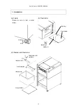
Page 55: ...AeroCut nano SERVICE MANUAL 55 12 Drawing 12 1 Drawing ...

Page 56: ...AeroCut nano SERVICE MANUAL 56 ...

Page 57: ...AeroCut nano SERVICE MANUAL 57 12 2 Board Details a PCB CPU board ...

Page 58: ...nsor Conveyor pulse motor Vacuum fan motor Blow fan motor Cutter motor Feed table motor Cover Limit switch 1 Cover Limit switch 2 Feed table lower limit switch Feed upper sensor Cutter upper limit switch DC power supply DC power supply Cutmark sensor Origin sensor Side Blow fan motor Belt motor ...

Page 59: ...r move forward D26 OUTPUT Cutter motor move reverse D27 OUTPUT Belt motor move forward D28 OUTPUT Belt motor move reverse D29 OUTPUT Side Blow fan motor D31 OUTPUT None D1 INPUT Origin sensor D5 INPUT Cut mark sensor D14 INPUT None D15 INPUT None D16 INPUT None D17 INPUT Cover limit switch 1 D18 INPUT Cover limit switch 2 D23 INPUT None D2 INPUT Feed table lower limit SW D6 INPUT Cutter upper limi...

Page 60: ...4 Power Supply for CPU TP5 Power Supply for Touch Panel TP6 Power Supply for Conveyor Pulse driver TP7 Ground TP8 Power Supply for Belt Pulse driver TP9 Power Supply for Output device TP10 Ground for Output device 5 V LED TP4 TP7 3 3V LED TP1 TP7 TP6 P 22 TP8 P 22 TP9 24 VX for OUTPUT TP10 X_GND for OUTPUT 24 V LED TP2 TP7 TP3 24 V TP7 GND TP2 24 V TP5 5 V TP4 5 V TP1 3 3 V ...

Page 61: ...AeroCut nano SERVICE MANUAL 61 UCHIDA YOKO CO LTD TOKYO JAPAN ...

Reviews: