AeroCut X / XPro SERVICE MANUAL
97
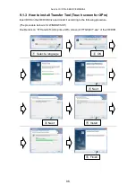
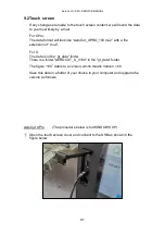
9.3
CPU board
・
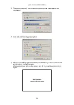
If any changes are made to the program content, we will send the data to you most likely
by e-mail.
・
The data format will look like “AeroCut_X_V100.hex” with a file extension of “.hex” .
・
The figure “100” refers to a version, which means Version 1.00.
・
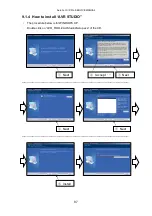
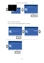
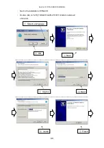
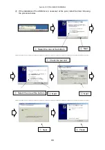
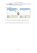
Save this data in a folder of your choice in your computer and upgrade the version as
follows. (The procedure below is for WINDOWS XP)
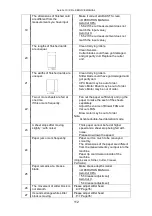
①
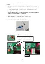
Remove the front cover and then the electrical component cover.
②
Connect the accessory of USB cable with Program writer.
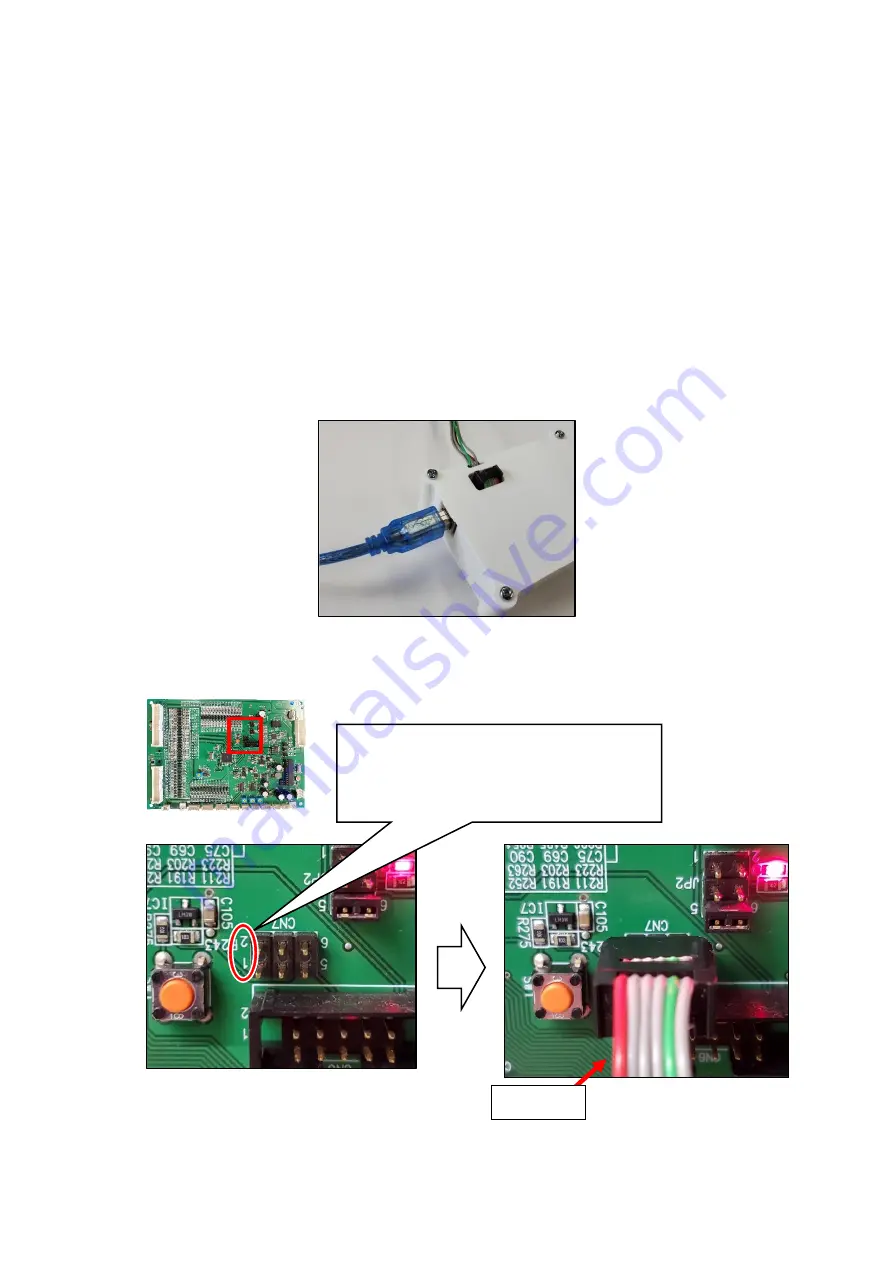
③
Connect the connector of Program writer to CN7 on the CPU board.
Must be connected the red wire of the
connector is on the 1 and 2 sides of
CN7.
Red wire
Summary of Contents for AeroCut X
Page 1: ...SERVICE MANUAL UCHIDA YOKO CO LTD TOKYO JAPAN V1 00 ...
Page 9: ...AeroCut X XPro SERVICE MANUAL 9 d Remove covers ...
Page 27: ...AeroCut X XPro SERVICE MANUAL 27 3 7MAINTENANCE Screen AeroCut XPro AeroCut X ...
Page 56: ...AeroCut X XPro SERVICE MANUAL 56 7 How to make layout 7 1General template mm ...
Page 57: ...AeroCut X XPro SERVICE MANUAL 57 7 2General template inch ...
Page 67: ...AeroCut X XPro SERVICE MANUAL 67 AeroCut XPro ...
Page 68: ...AeroCut X XPro SERVICE MANUAL 68 AeroCut XPro ...
Page 69: ...AeroCut X XPro SERVICE MANUAL 69 AeroCut X ...
Page 70: ...AeroCut X XPro SERVICE MANUAL 70 AeroCut X ...
Page 71: ...AeroCut X XPro SERVICE MANUAL 71 AeroCut X ...
Page 81: ...AeroCut X XPro SERVICE MANUAL 81 8 5Wiring Details ...
Page 82: ...AeroCut X XPro SERVICE MANUAL 82 ...
Page 113: ...UCHIDA YOKO CO LTD TOKYO JAPAN ...